Mars Rover
Introduction
The Canadian International Rover Challenge (CIRC) held in Drumheller, AB and the University Rover Challenge (URC) held in Hanksville, UT are two competitions where university student teams design and build a Mars Rover prototype. The teams compete in simulated tasks similar to tasks required of a rover on Mars. Such tasks are Autonomous Navigation, Soil Sampling, or Search & Rescue. In any given task, a rover chassis and suspension are required to house motor controllers, communication radios, and various microcontrollers. The rover needs to support auxiliary equipment such as a robotic arm, science soil collection drill, or a front loader for large surface soil samples.
Project Background
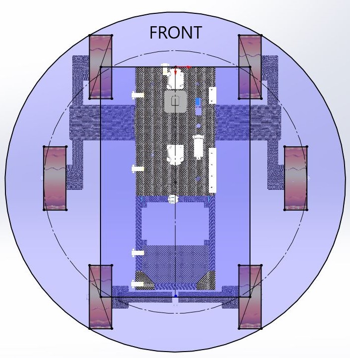 One common style of
rover suspension is the tiple bogey suspension. Three independent, non-actuated, and
free pivoting suspension arches are configured about the rover. The triple bogey allows for the
independent arches to contort easily to the terrain while maintaining a level chassis. Steep and uneven
terrain can be easily tackled. The center wheels, as seen from a top view on the right, are offset to
the outside which results in a smoother skid steer (turning) operation.
One common style of
rover suspension is the tiple bogey suspension. Three independent, non-actuated, and
free pivoting suspension arches are configured about the rover. The triple bogey allows for the
independent arches to contort easily to the terrain while maintaining a level chassis. Steep and uneven
terrain can be easily tackled. The center wheels, as seen from a top view on the right, are offset to
the outside which results in a smoother skid steer (turning) operation.
Prototyping
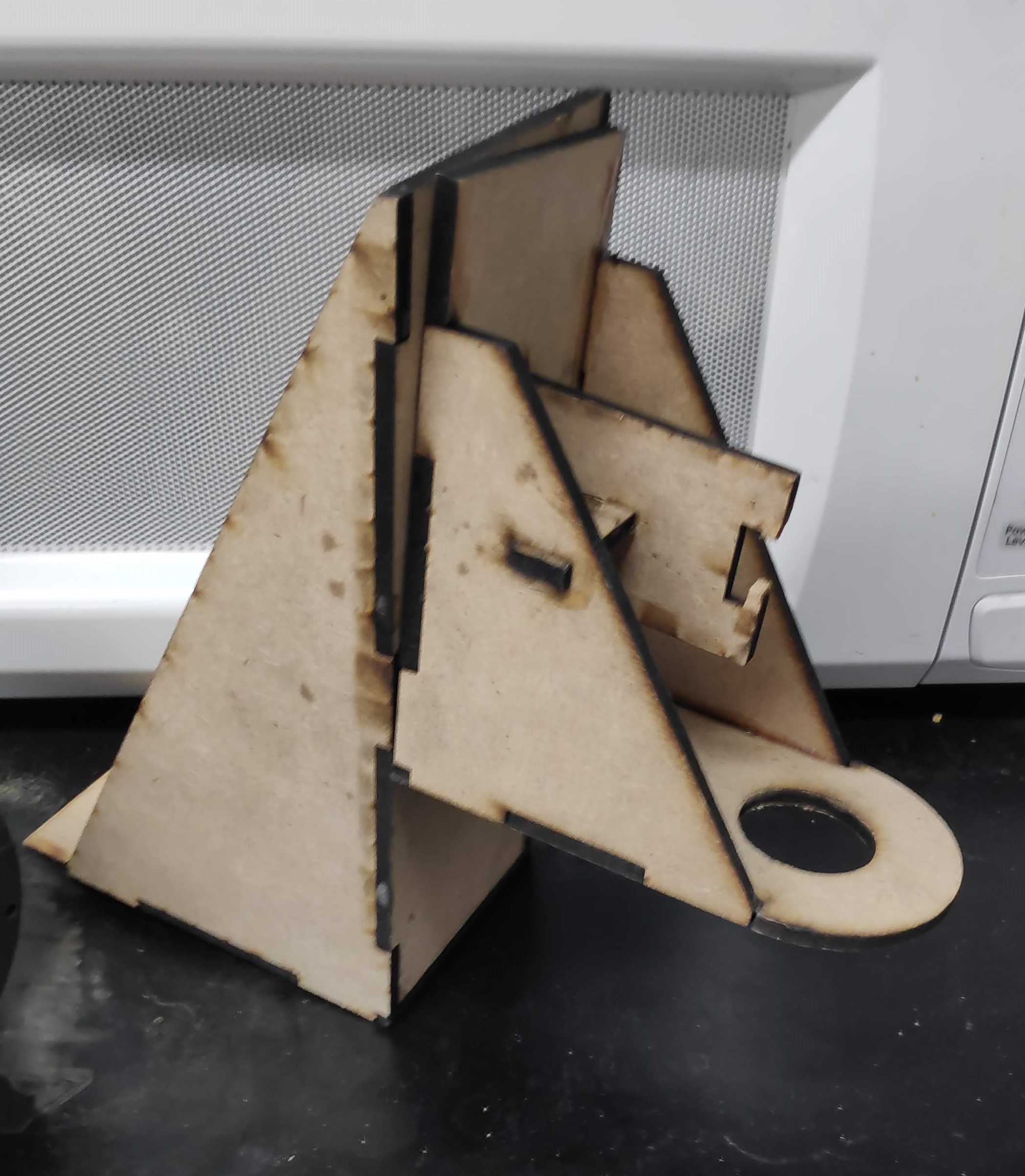
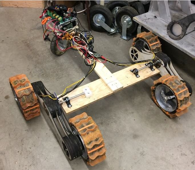 The geometry of the
suspension, the wheel distances and pivot height off the ground, was determined from various papers
making it pretty theoretical. Building a prototype suspension was a great idea to validate the
theoretical geometry quickly and cheaply. The prototype was made from laser-cut plywood sheets laminated
together. The worst-case scenario for steering and turning would be when the rover is at its lightest configuration, around
30kg. The rear arch was free to pivot to further amplify issues with the front left and right
arches. Testing revealed that on high friction surfaces (asphalt) and with a zero-turn radius, the
arches would lift up and could cause potential damage to the rover. Given the terrain is loose dirt or
rocks, and typical driving is slight turning, the geometry was deemed acceptable.
The geometry of the
suspension, the wheel distances and pivot height off the ground, was determined from various papers
making it pretty theoretical. Building a prototype suspension was a great idea to validate the
theoretical geometry quickly and cheaply. The prototype was made from laser-cut plywood sheets laminated
together. The worst-case scenario for steering and turning would be when the rover is at its lightest configuration, around
30kg. The rear arch was free to pivot to further amplify issues with the front left and right
arches. Testing revealed that on high friction surfaces (asphalt) and with a zero-turn radius, the
arches would lift up and could cause potential damage to the rover. Given the terrain is loose dirt or
rocks, and typical driving is slight turning, the geometry was deemed acceptable.
Manufacturing
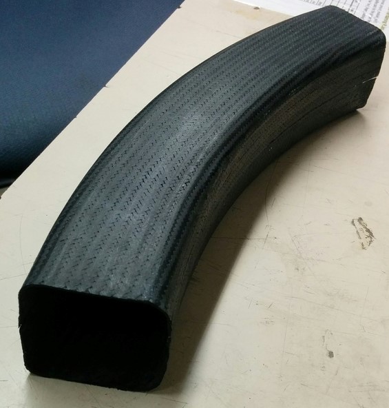 Testing
the manufacturing method for the suspension arches. Two "C-Channel" halves are made individually and
combined by several carbon fiber strips bonded on the insides of the seams.
Testing
the manufacturing method for the suspension arches. Two "C-Channel" halves are made individually and
combined by several carbon fiber strips bonded on the insides of the seams.
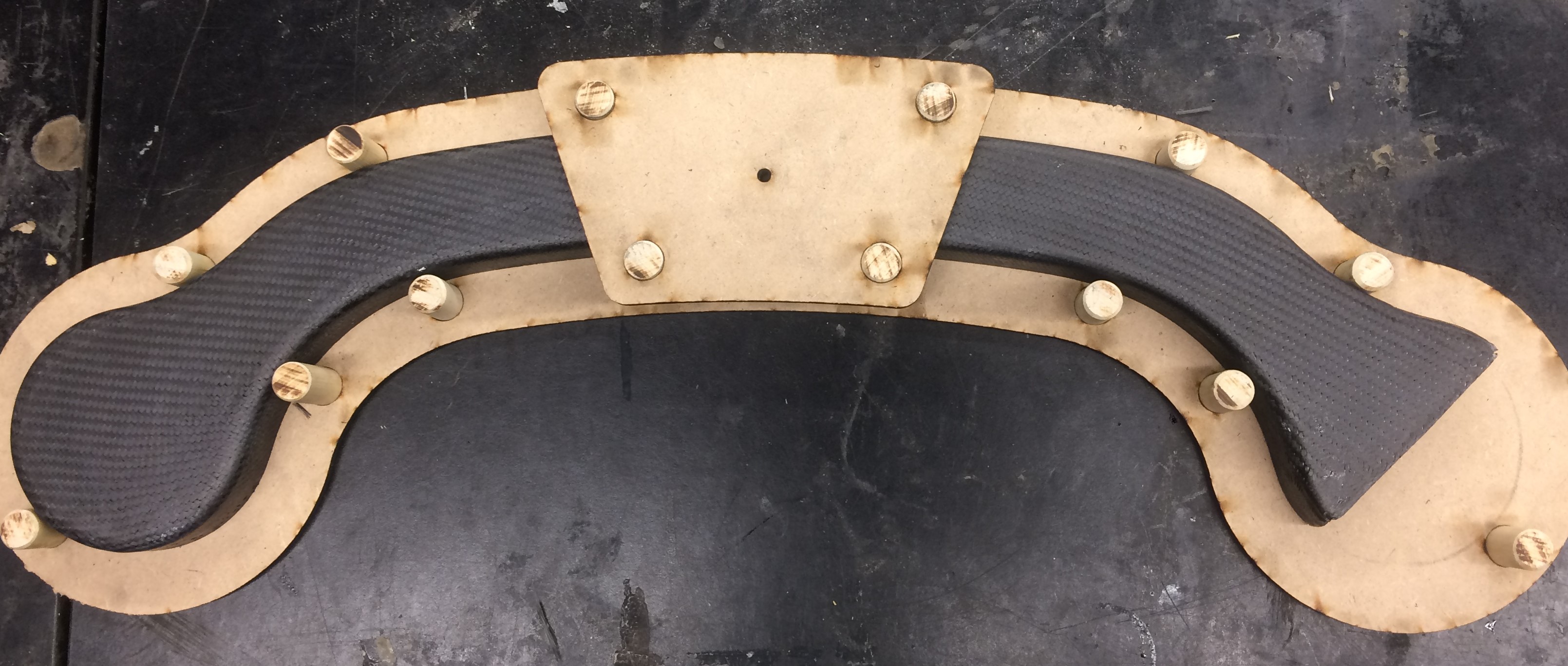
This jig was used to trim the two halves (C-Channel) of the
suspension arches to their final height by holding a dremel with a cut-off disc.
Laser cut jigs were used to accurately drill the position of the pivot for the arches. The jig for the
side arches is shown below.
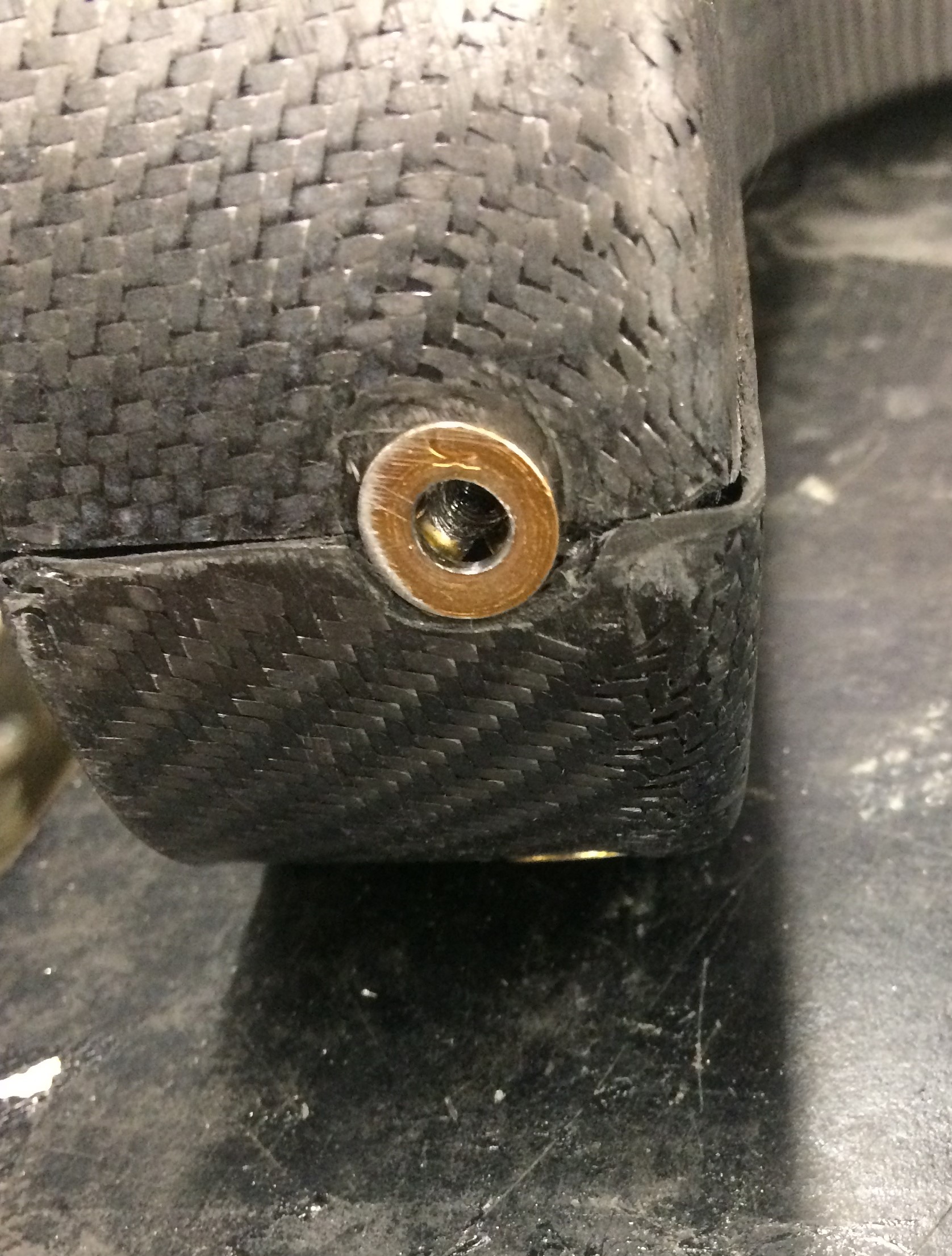
Rivet nuts were inserted into the suspension arches to allow the motor housings to be secured to the
suspension.
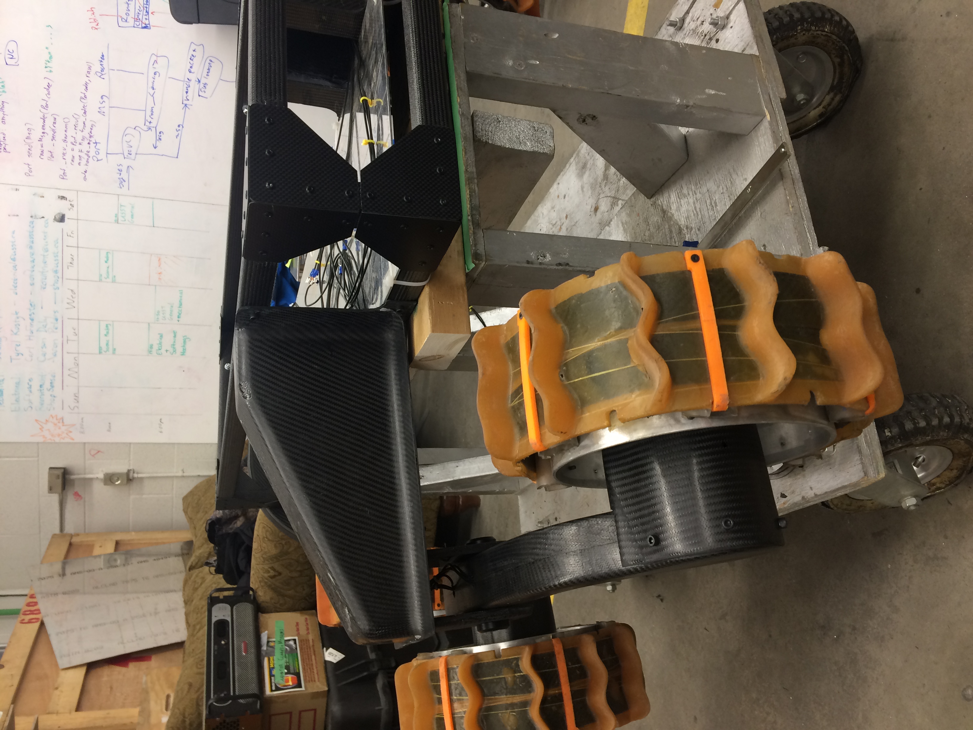
A simple rectangular chassis was made from purchased square carbon fiber tubes, gusset plates, rivets,
and epoxy. The suspension arms have foam-cored carbon fiber forks to attach to the suspension arches.
The suspension arches have internal wiring to be connected to two brushless DC motors and the wheels.
The wheels have aluminum rims and spokes with a thick urethane tread. The tread has inlaid carbon fiber
strips for shape retention and is stitched together with Kevlar thread. The wheels play a large role in
passive shock absorption when dealing with rough terrain.
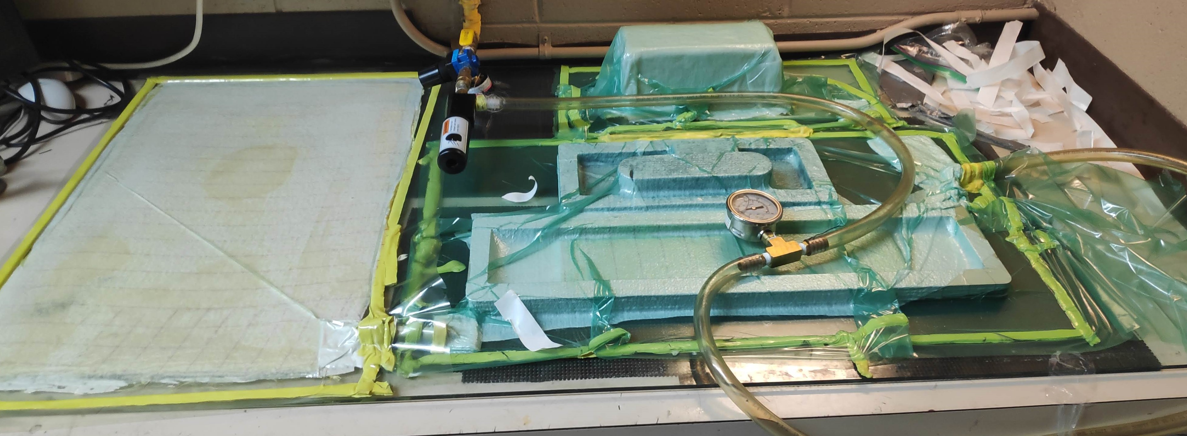
Below is an image of a composites lay-up using a vacuum bag setup. There are four parts in three
separate bags. Here I am making a Kevlar plate for the electrical enclosure lid, a Kevlar battery box,
and a carbon fiber front and side panel.
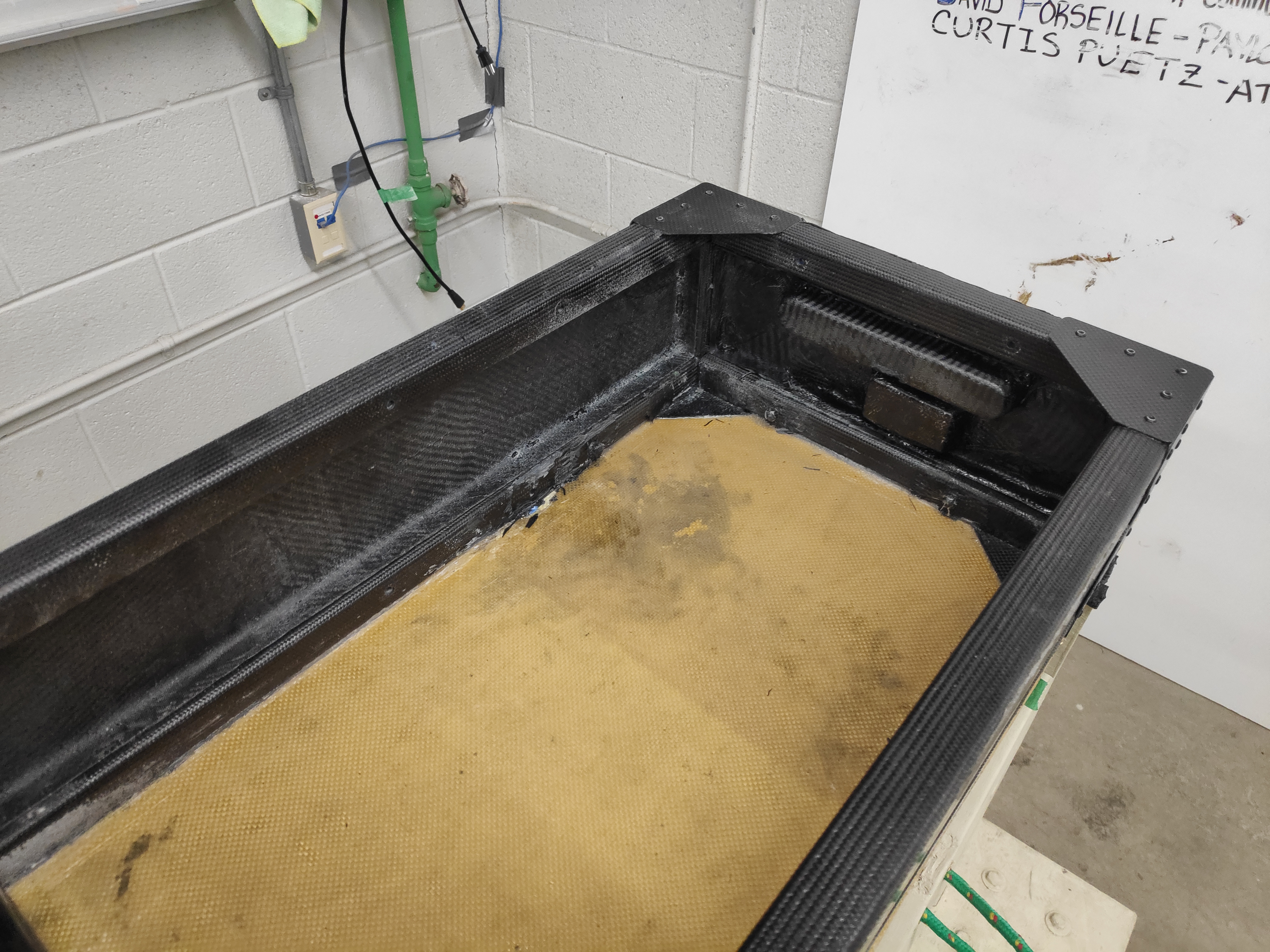
Lightweight carbon fiber panels were added to the front half of the rover to create an electrical
enclosure. The panels will keep the elements, dust or water, out of from the electronics. The foam-cored
Kevlar skid plate (yellow panel on the bottom of the chassis) can also be seen here.
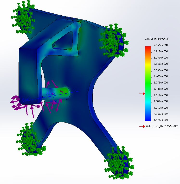
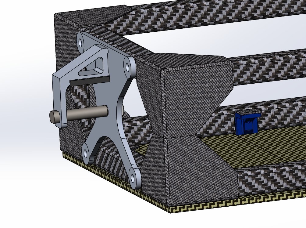
The rear suspension connection is the only structural aluminum used on the frame. The CAD model and FEA
for the
rear suspension pivot can be seen below. The FEA showed failure at the worst-case scenario of a 1+ meter
drop with a 50kg rover, however, this being a very unlikely scenario, the design was acceptable.
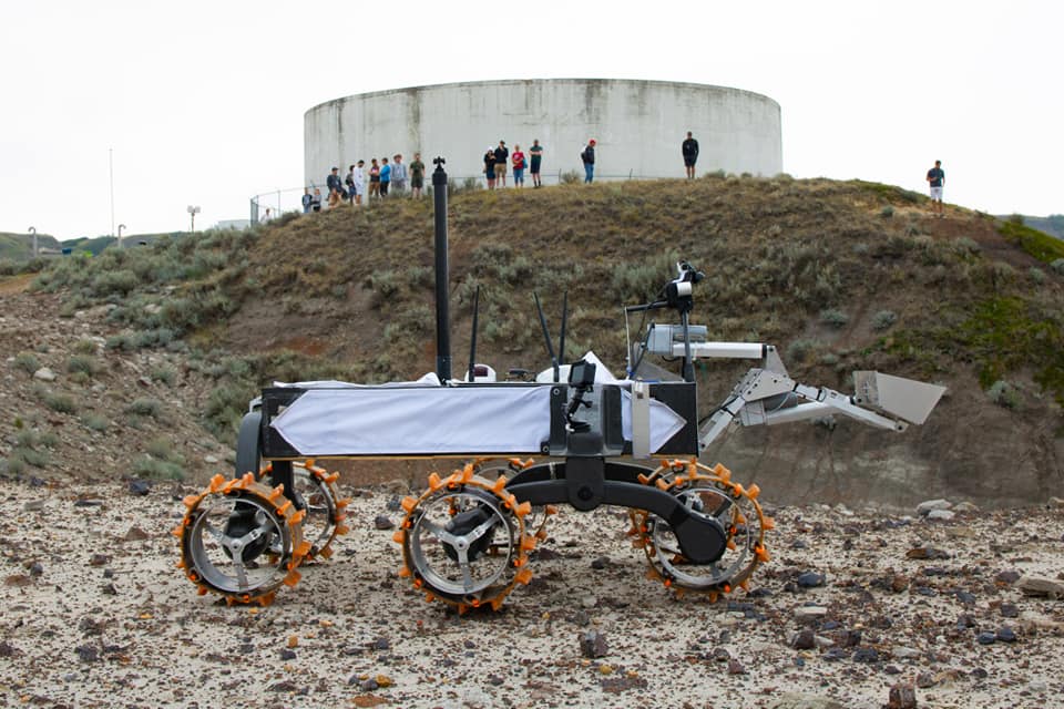
The full rover chassis, suspension, and electrical enclosure can be seen below at the 2019 CIRC Night
Task.
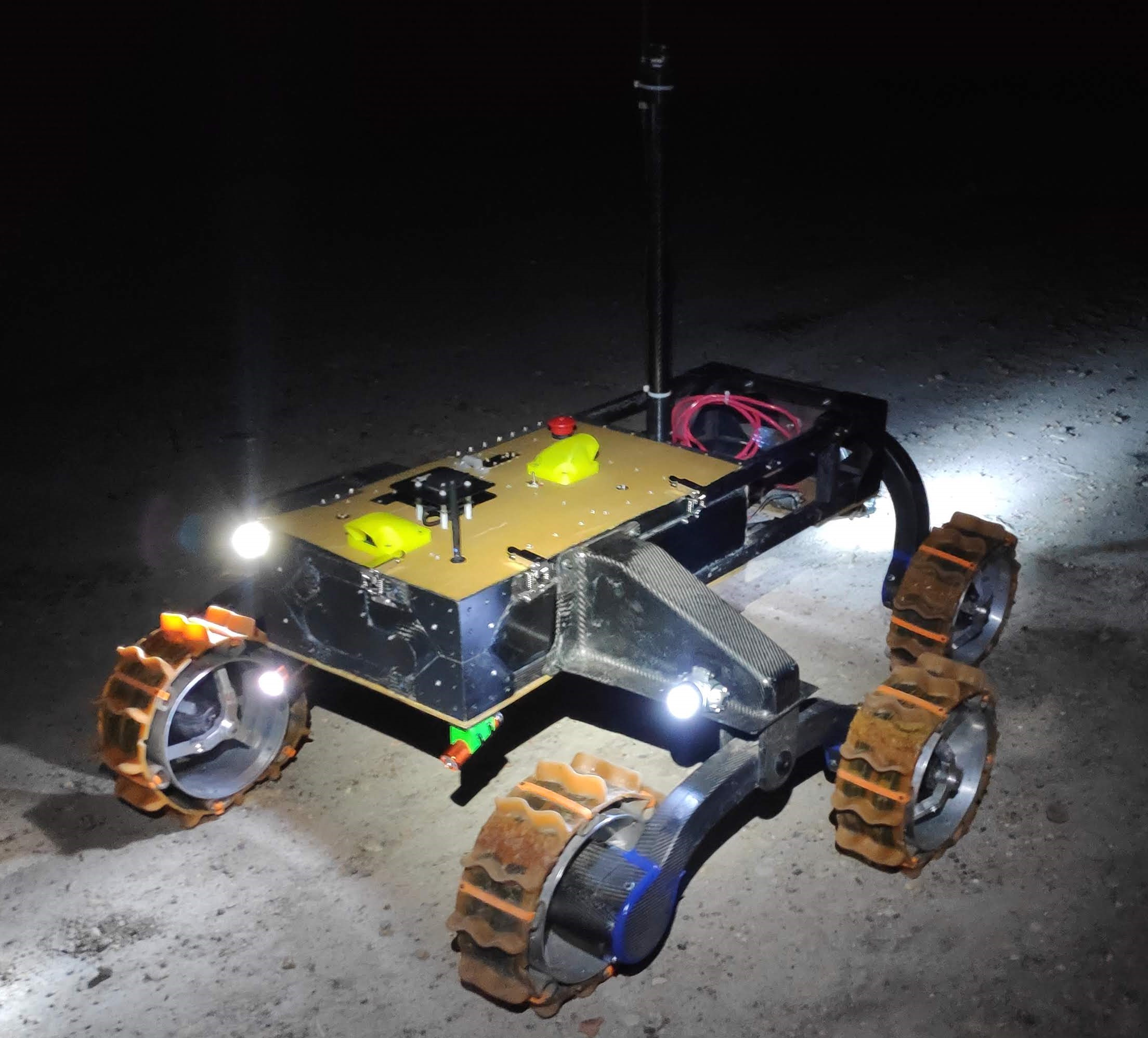 The rover can tackle large obstacles easily with the superior suspension design, high torque motors, and
grippy wheels!
The rover can tackle large obstacles easily with the superior suspension design, high torque motors, and
grippy wheels!
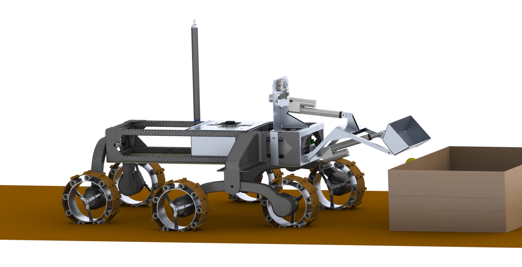
Front Loader
One of the tasks for the CIRC competition required taking larger surface soil samples of 4kg's for
various locations. I designed, prototyped, and fabricated a front loader that quickly attached to the
front of the rover. The CAD design can be seen below.
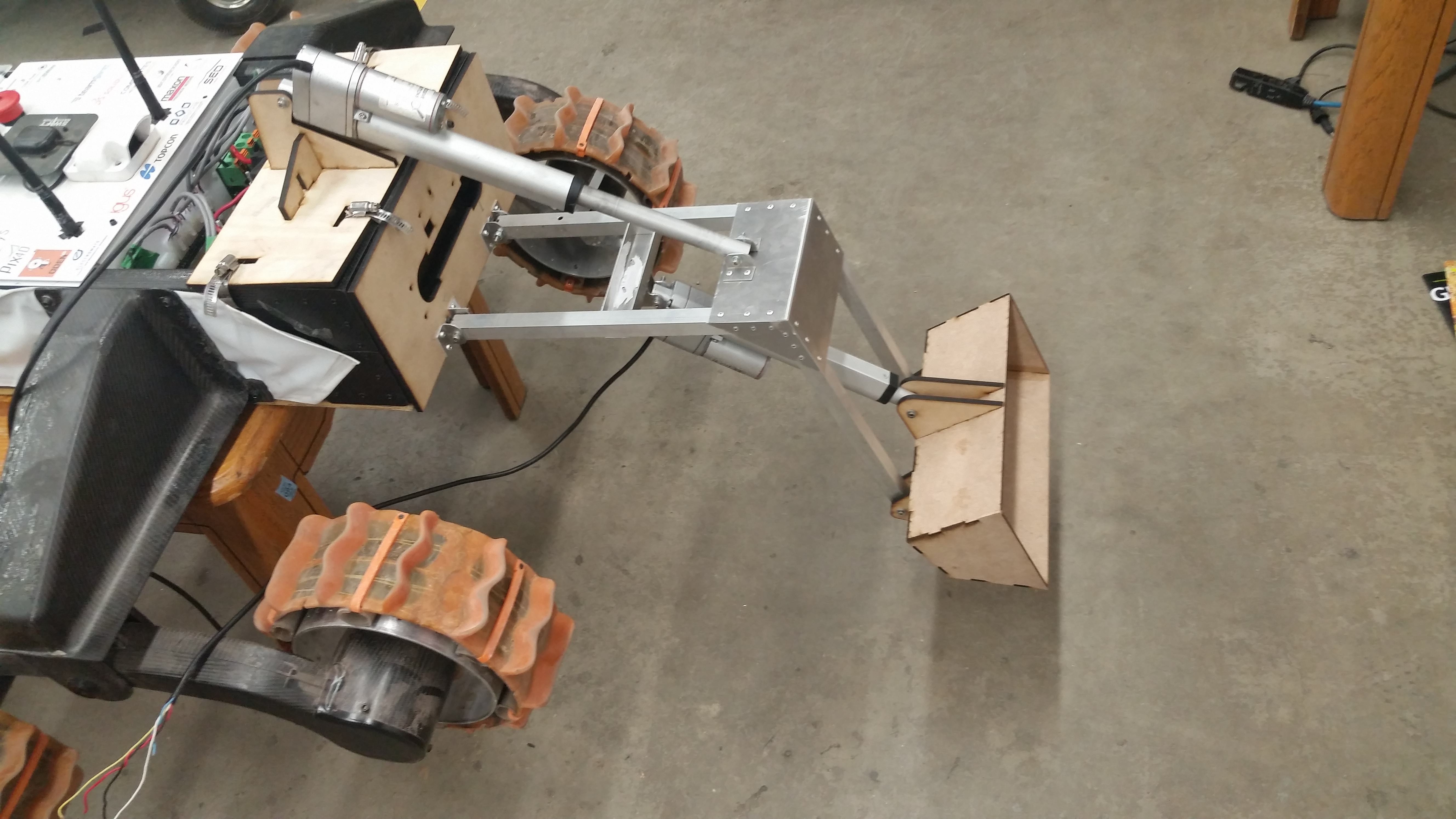
To ensure that the center of mass was acceptable, a prototype was quickly and cheaply built using
aluminum square tube and laser-cut MDF. The two linear actuators were more than strong enough to lift a
full load of soil. The amount of soil collected was measured using two calibrated
load cells which were built into the frame of the front loader.
 The front loader and rover can be seen below at the 2019 CIRC competition.