Robotic Arm
Introduction
The Canadian International Rover Challenge (CIRC) held in Drumheller, AB and the University Rover Challenge (URC) held in Hanksville, UT are two competitions where university student teams design and build a Mars Rover prototype. The teams compete in simulated tasks similar to tasks required of a rover on Mars. Such tasks are called Extreme Retrieval and Delivery Mission or Equipment Servicing or Search & Rescue where a teleoperated rover is required to interface with its surroundings. The use of a robotic arm is essential to access and manipulate objects in the rover’s immediate area accurately and easily. There are many considerations and requirements when designing a robotic arm. From competition guidelines and working of past designs of robotic arms, here are a few requirements that this arm was designed to:
The Design
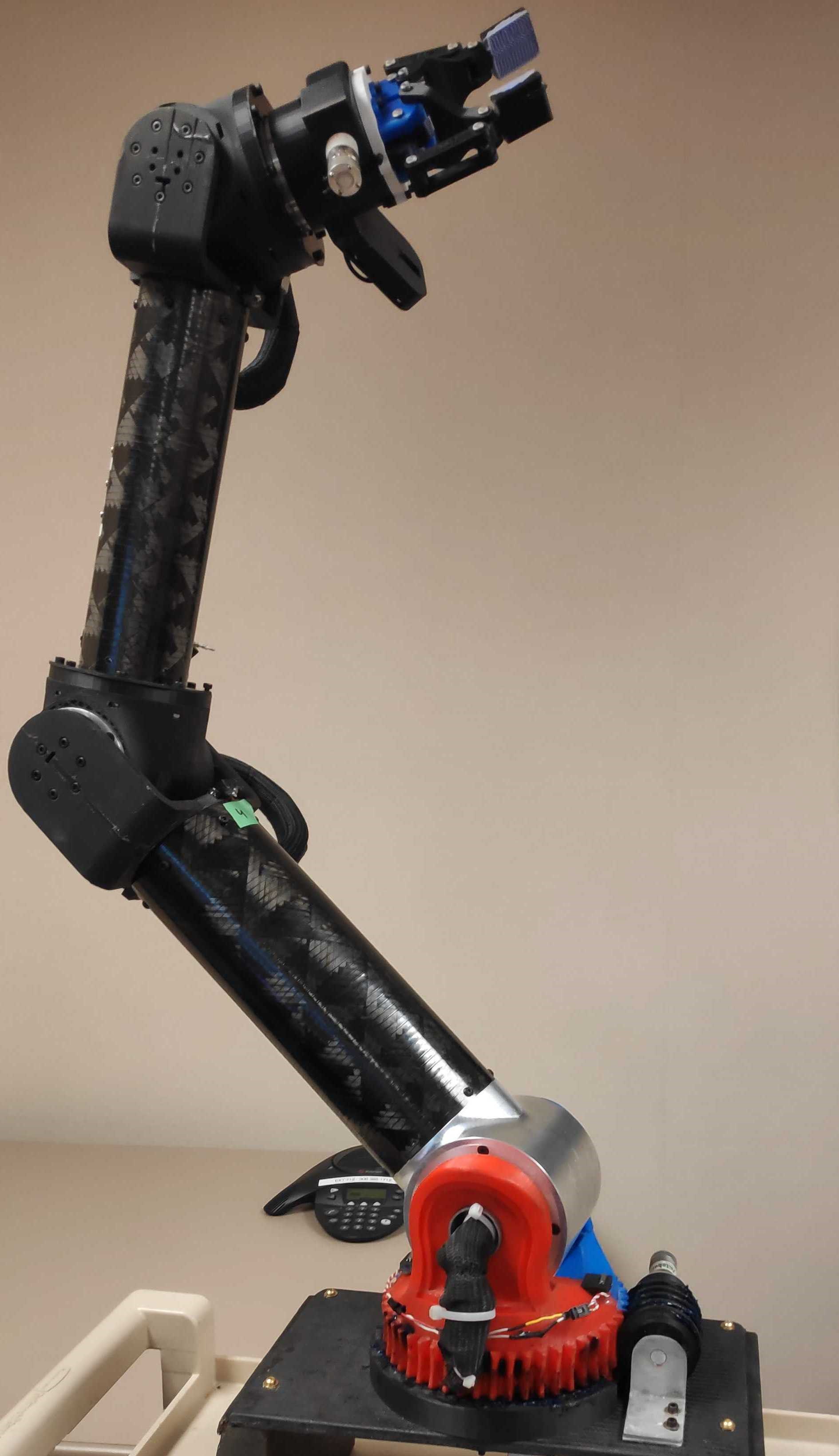
The arm used a combination of carbon fiber tubes and plates, CNC machined aluminum parts, and 3-D printing for the main construction. The three main joints of the arm are the shoulder, elbow, and wrist. Each joint has two degrees of freedom, rotational and translational. Working from the bottom up, each of the six axes will be described below.
Axis 1 - Shoulder Rotation
The base of the arm is paramount as it provides the rigidity for the rest of the arm. The first iteration of the design used a large 3-D printed U-Support and worm gear, shown below. The assembly interfaced with the rover via a stiff foam-cored carbon fiber plate. The U-Support rested on a bearing plate. The large base provided a stable foundation. The design was scrapped after prototyping due to its large mass, poor quality of the 3-D printed worm gear and drive causing jamming, issues with cable routing through the part, and the retention cap needed a needle bearing for smoother operation.
The final iteration used a bent aluminum bracket to support the arm and was driven by a spur gear, as seen below. Although the area base is smaller, the design proved to be sufficiently rigid when driving over rough terrain. This version also addressed aforementioned issues by reducing the mass, having a smoother operation, and easier cable routing.
Axis 2 - Shoulder Translation
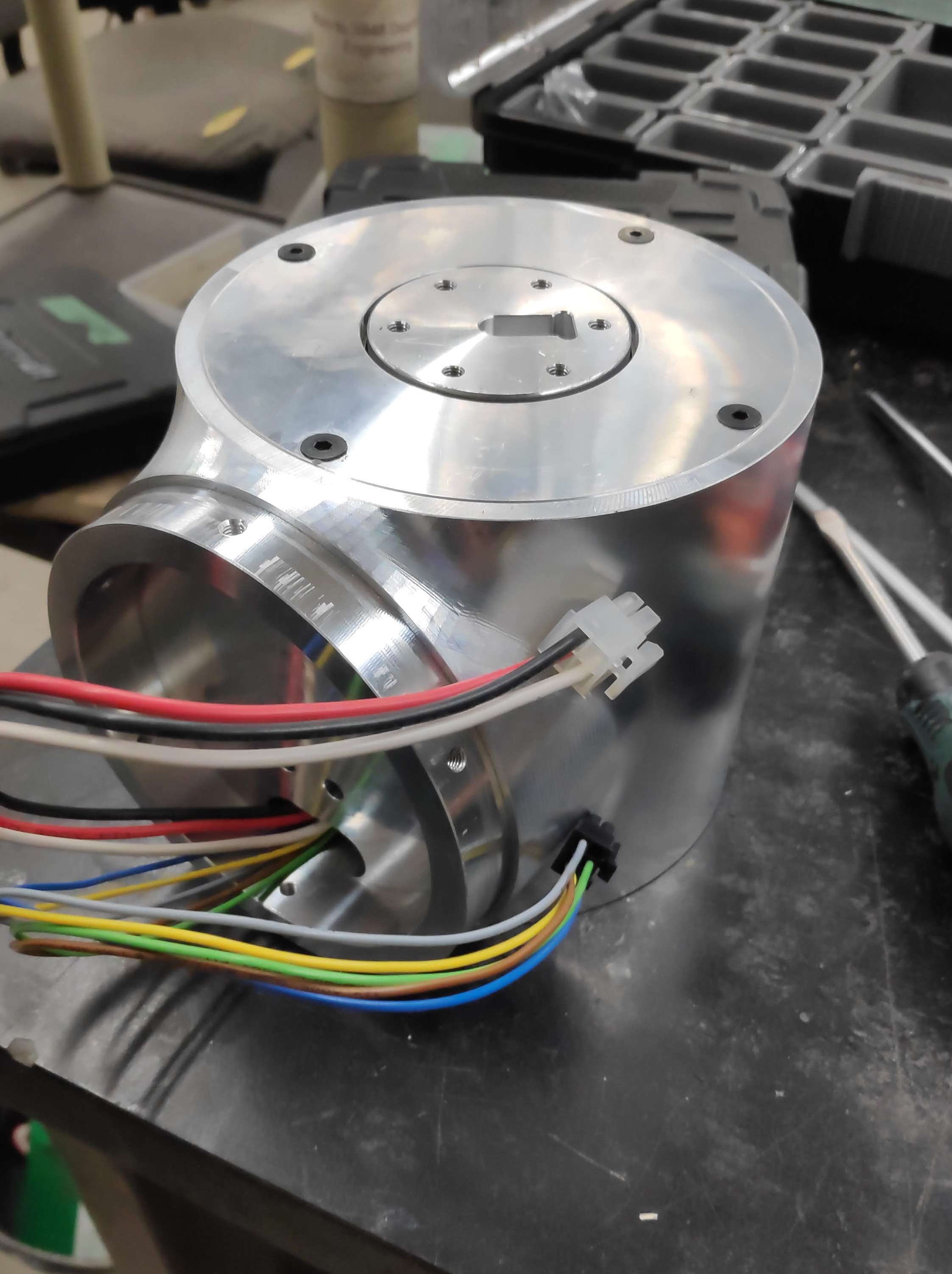
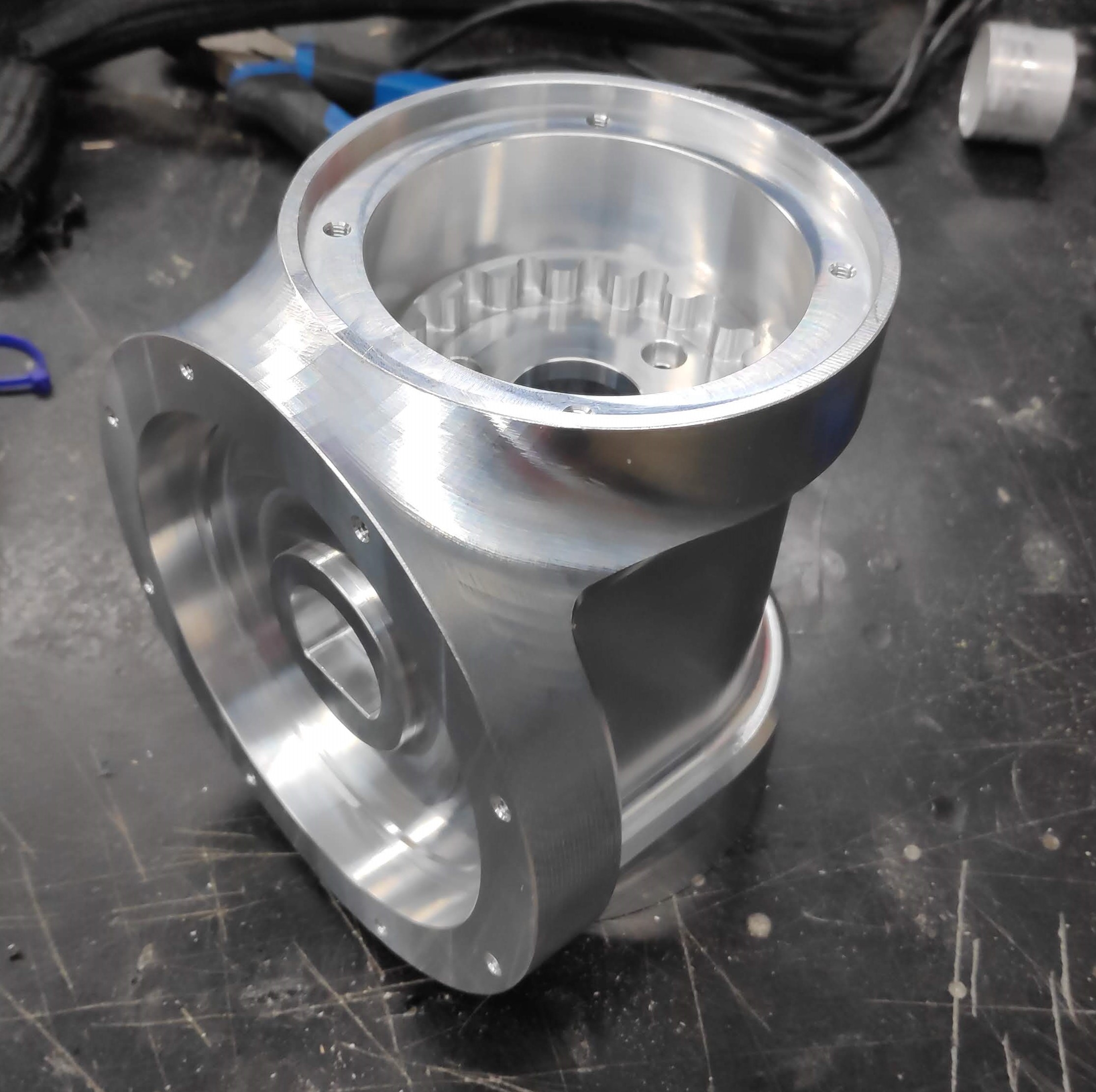
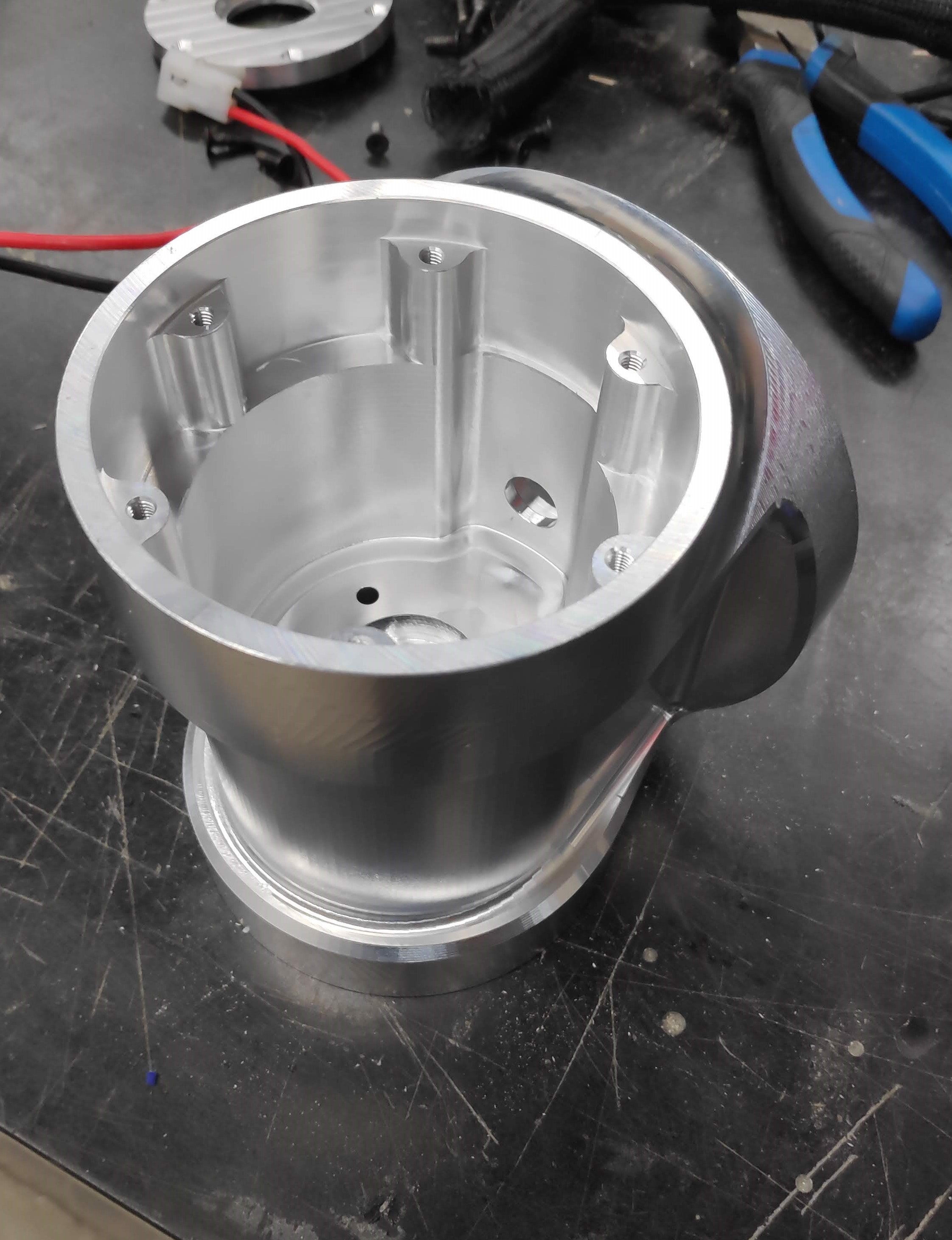
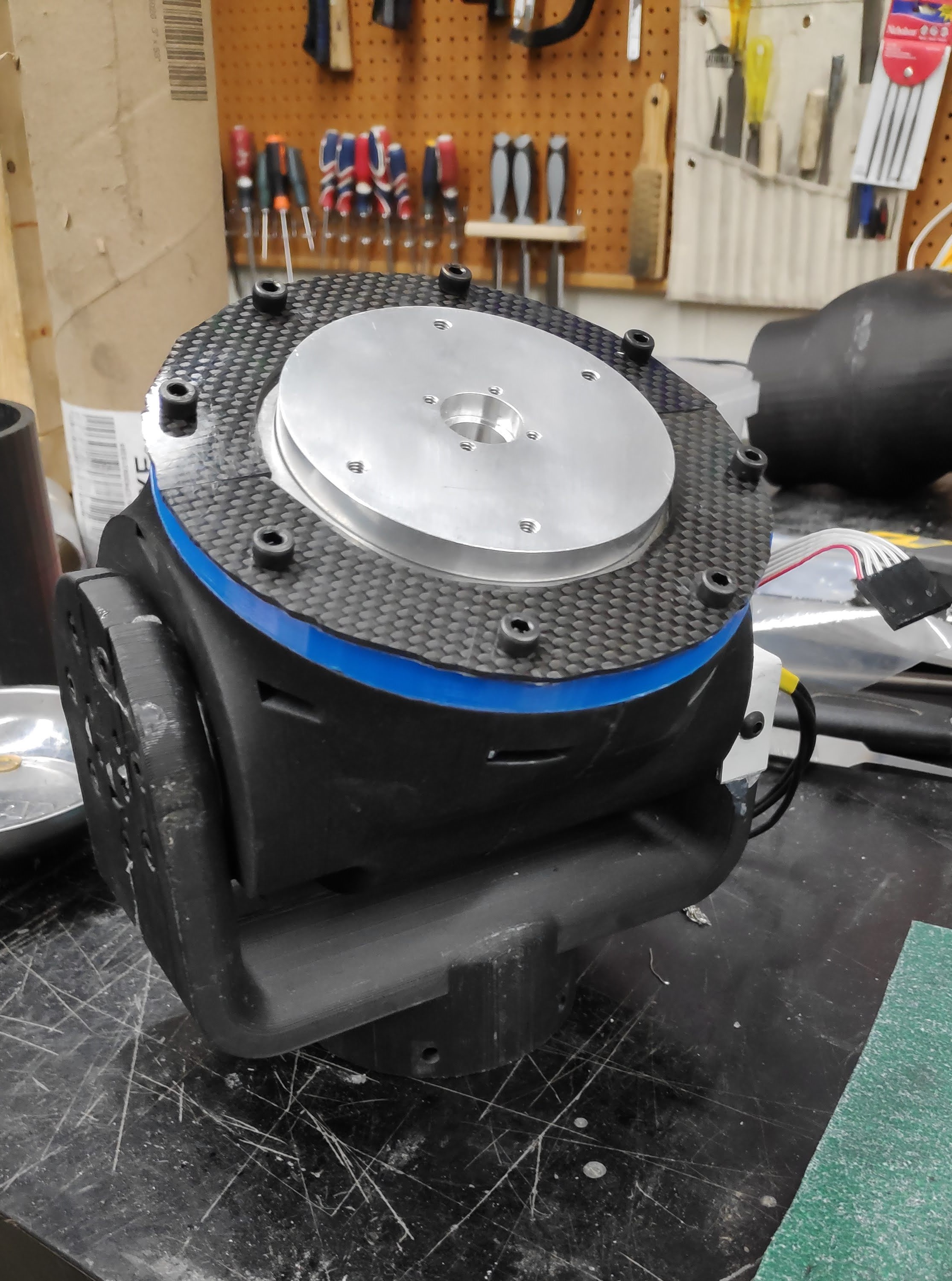
The three translational axes will see the largest load requirements having to lift both the arm itself and the payload. A gearbox is required to reduce the motor output speed and increase the output torque. Gearboxes can be (for our gear reduction of ~250:1) expensive, heavy, and are not common in a flange output style. Experiments on a new style gearbox, called a cycloidal gearbox, was complete by previous team members with promising results.
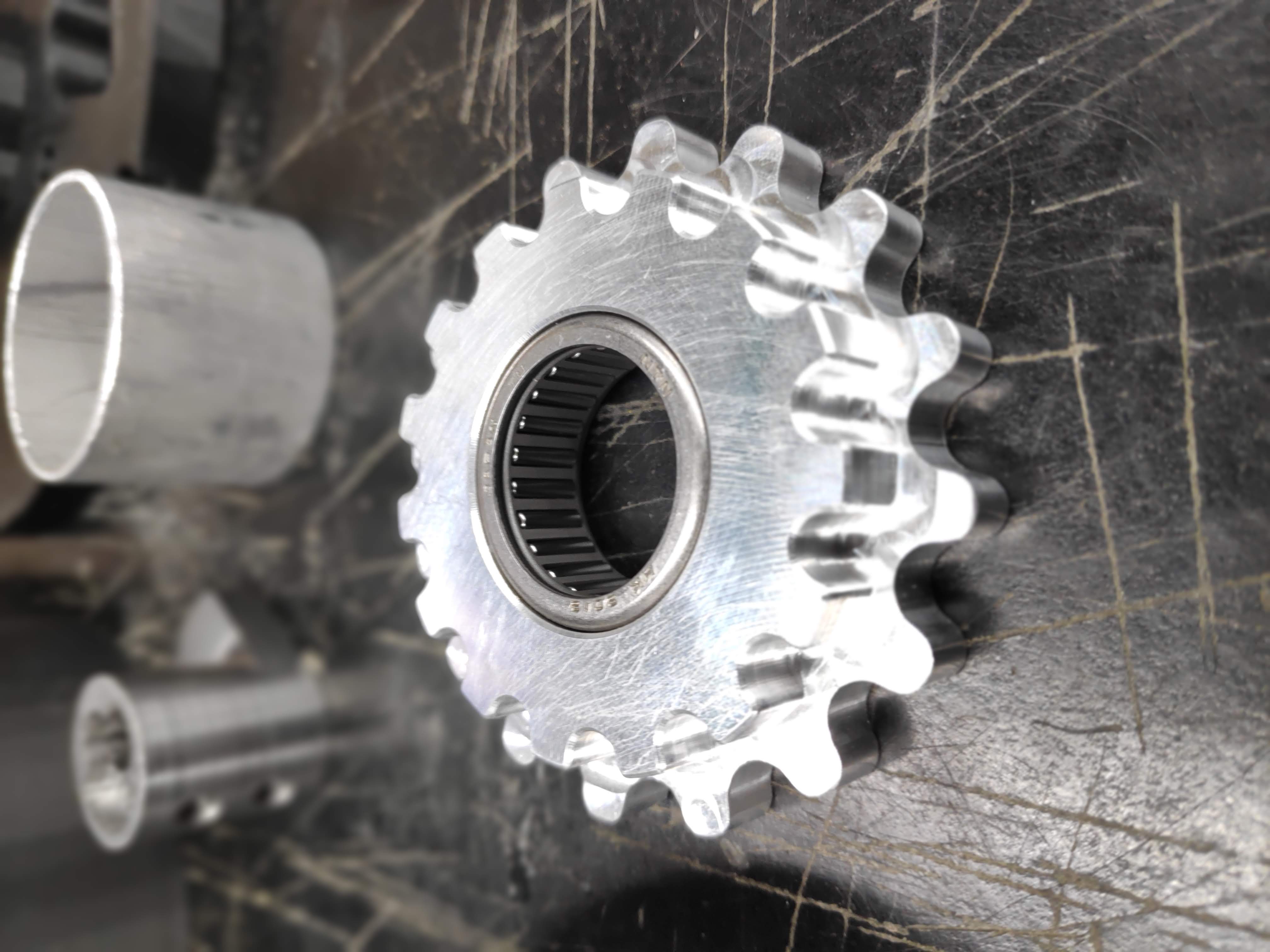
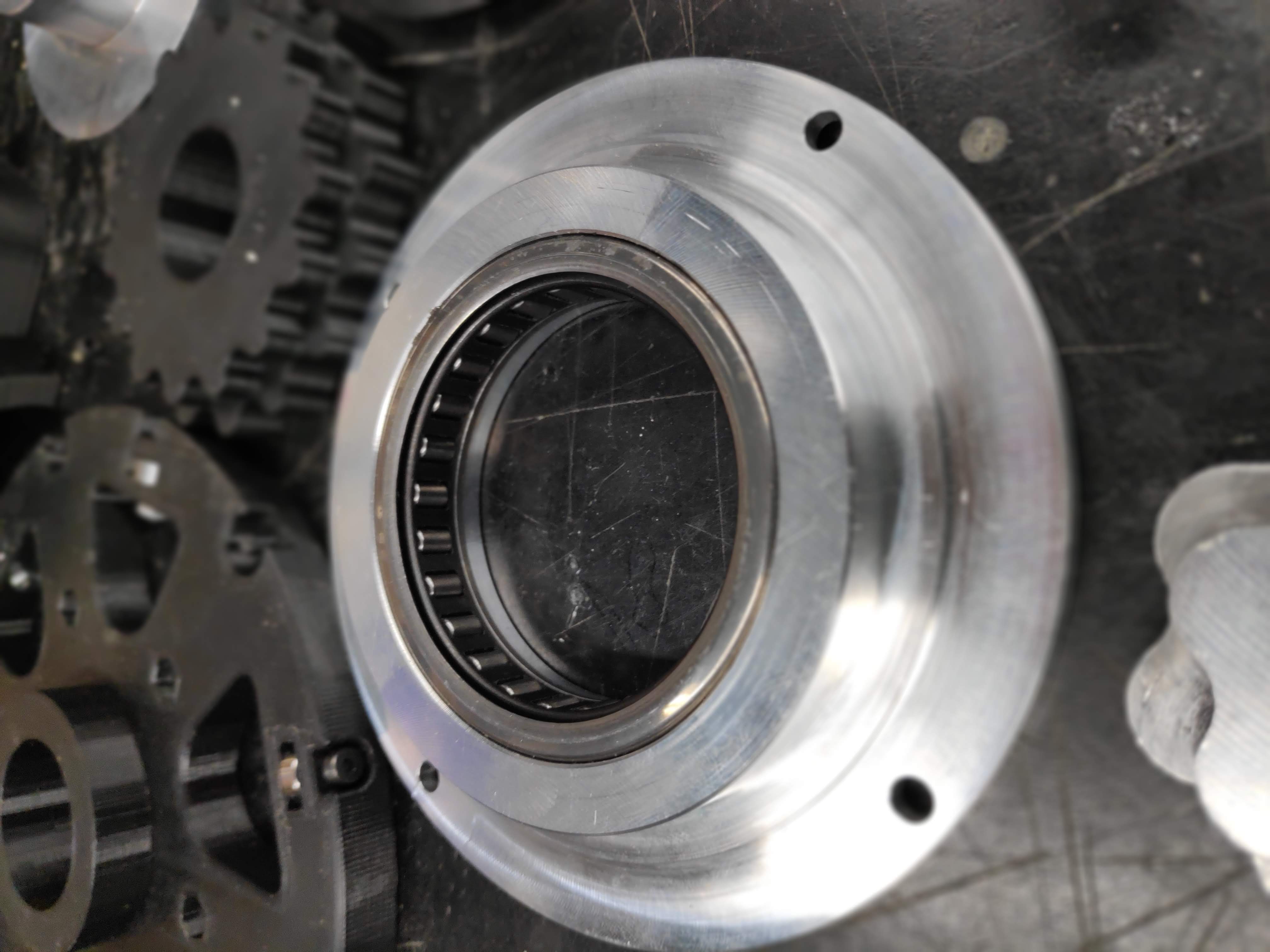
A cycloidal gearbox uses an eccentric spinner on the motor shaft to spin a two-stage rotor. The lower stage pushes off the motor housing. The upper stage rotates the output flange, resulting in a custom gear ratio, easily manufacturable, efficient, and compact gearbox. Below is an annotated image of the different parts of the gearbox. The gearbox below has a 256:1 reduction.
Axis 3 - Elbow Translation
The elbow translation axis has the same concept as the shoulder translation axis, also with a 256:1 reduction but a smaller motor. An annotated CAD image can be seen below.
Axis 4 - Elbow Rotation
The elbow rotation uses a small DC motor to rotate itself and the rest of the arm around a fixed gear, with respect to the elbow motor housing. A needle bearing and a thrust bearing ensure good alignment and smooth rotation under load.
Axis 5 & 6 - Wrist Translation and Rotation
Axis 5 & 6 have the same concepts as the elbow joint, using a cycloidal gearbox for the translational reduction and a spur gear driven rotation. Below is an annotated drawing of the fifth and sixth axes.
Manufacturing
The CNC machined aluminum parts were made from 6061-T6 aluminum. 3-D printed parts were made from a carbon fiber infused PLA, resulting in tougher and more durable parts over regular PLA.
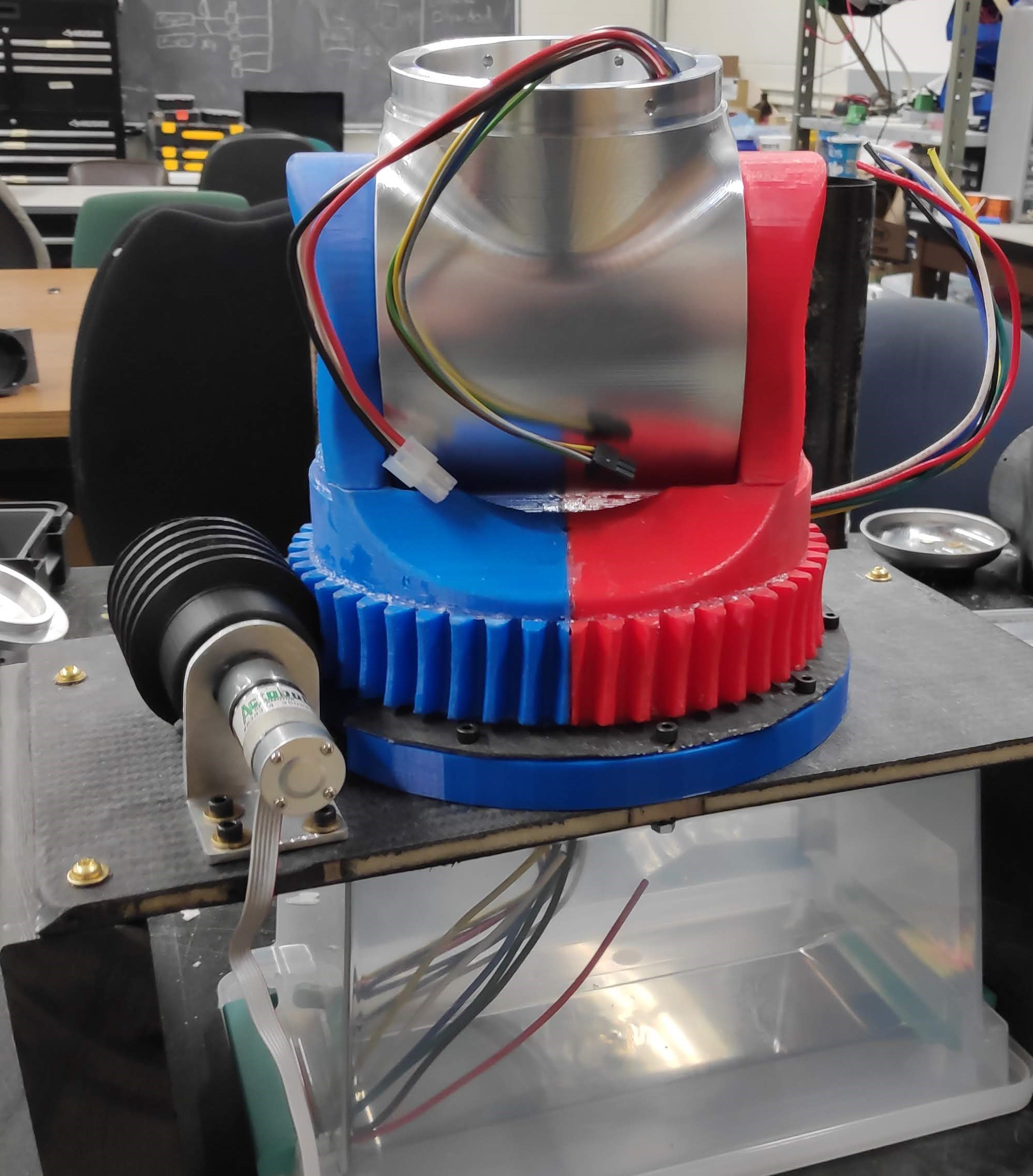
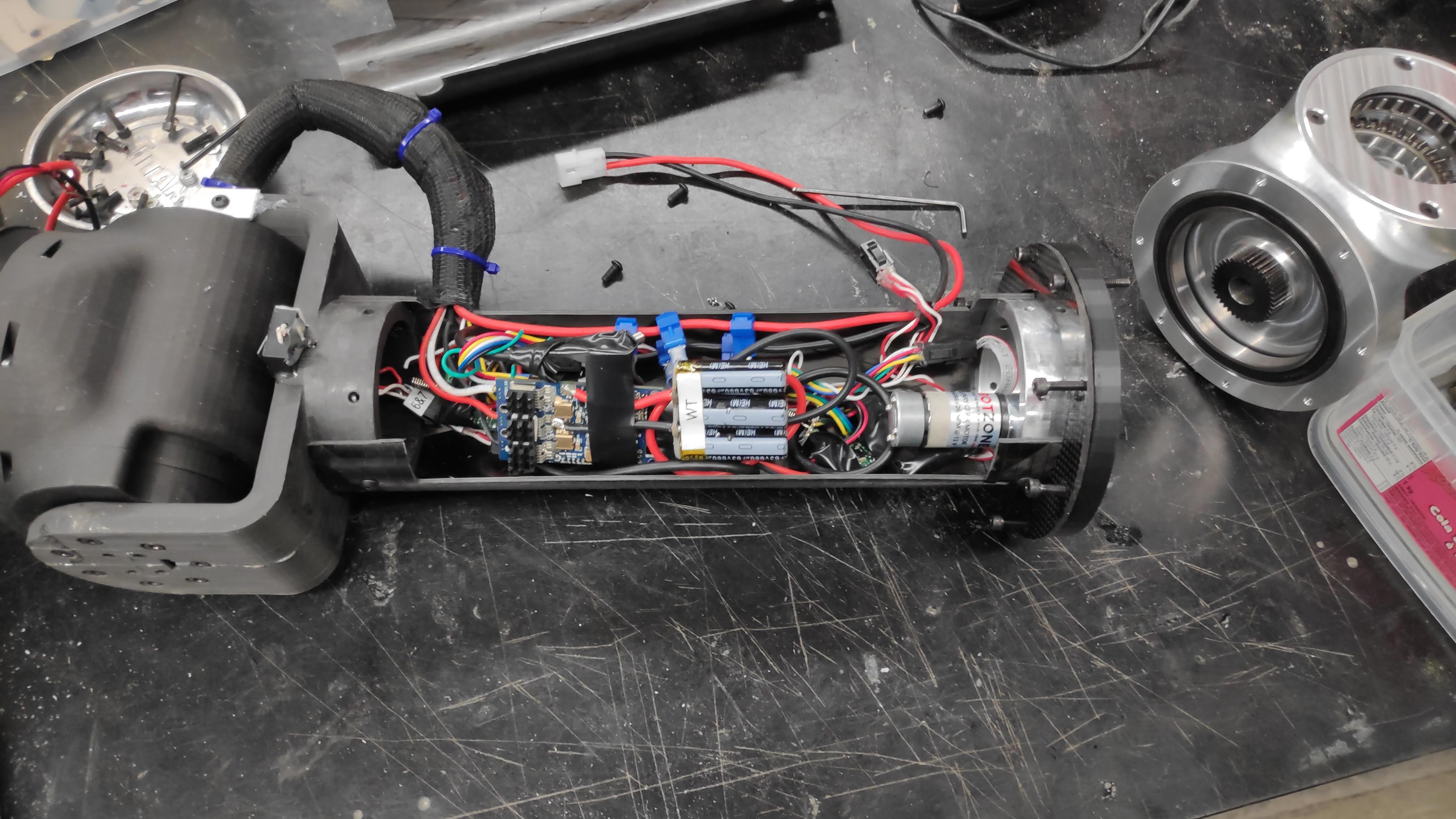
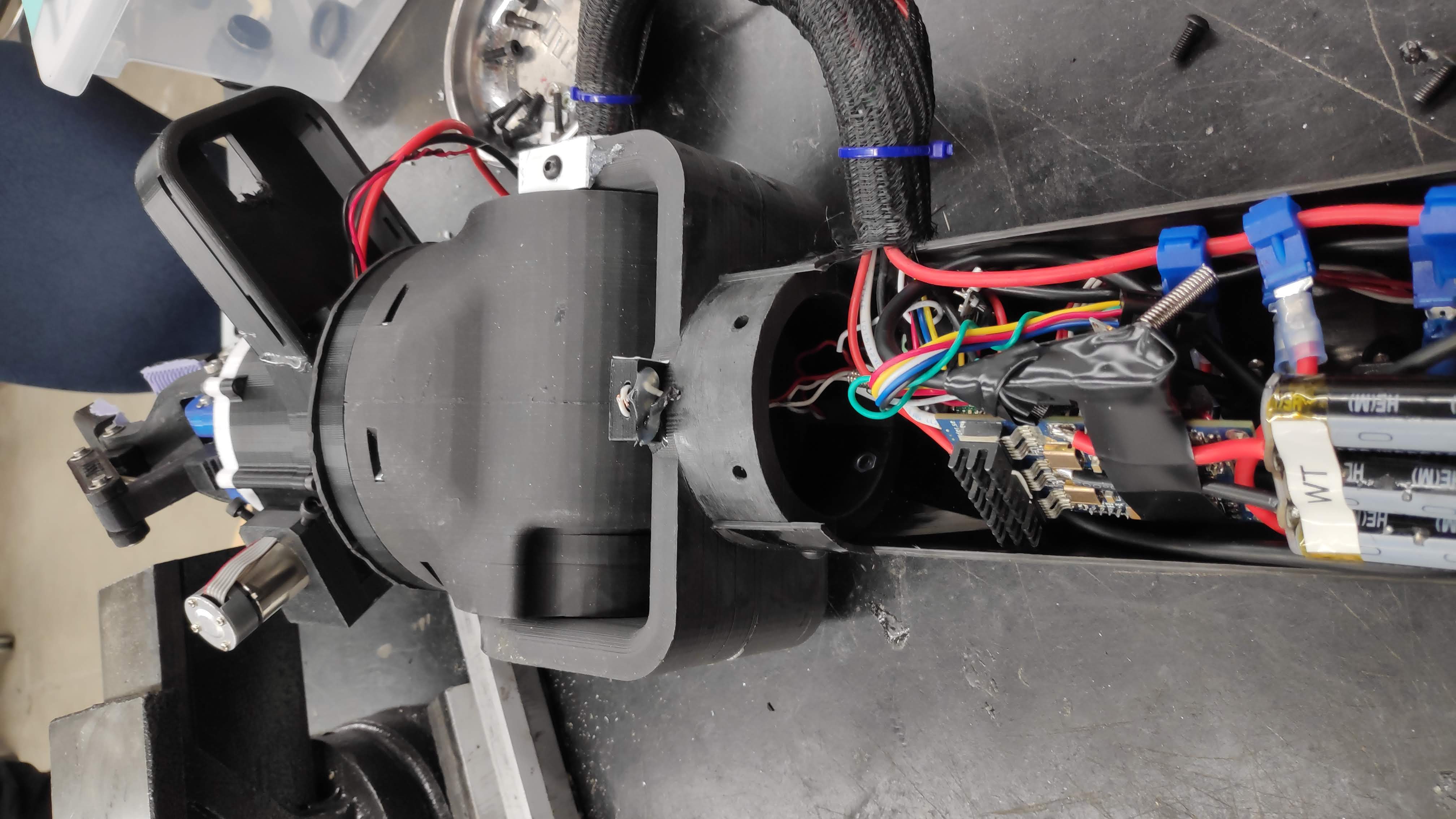
Testing the wrist motion!
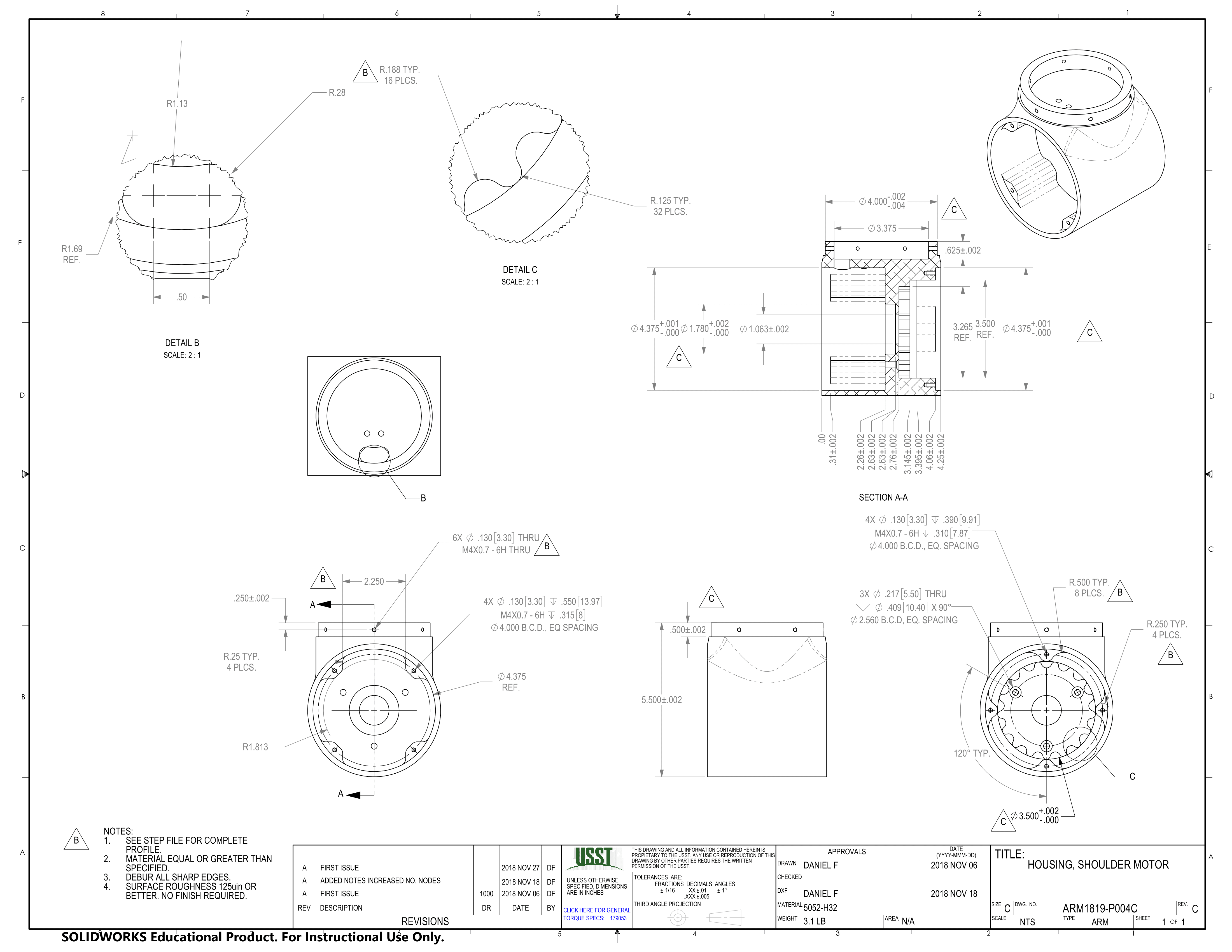
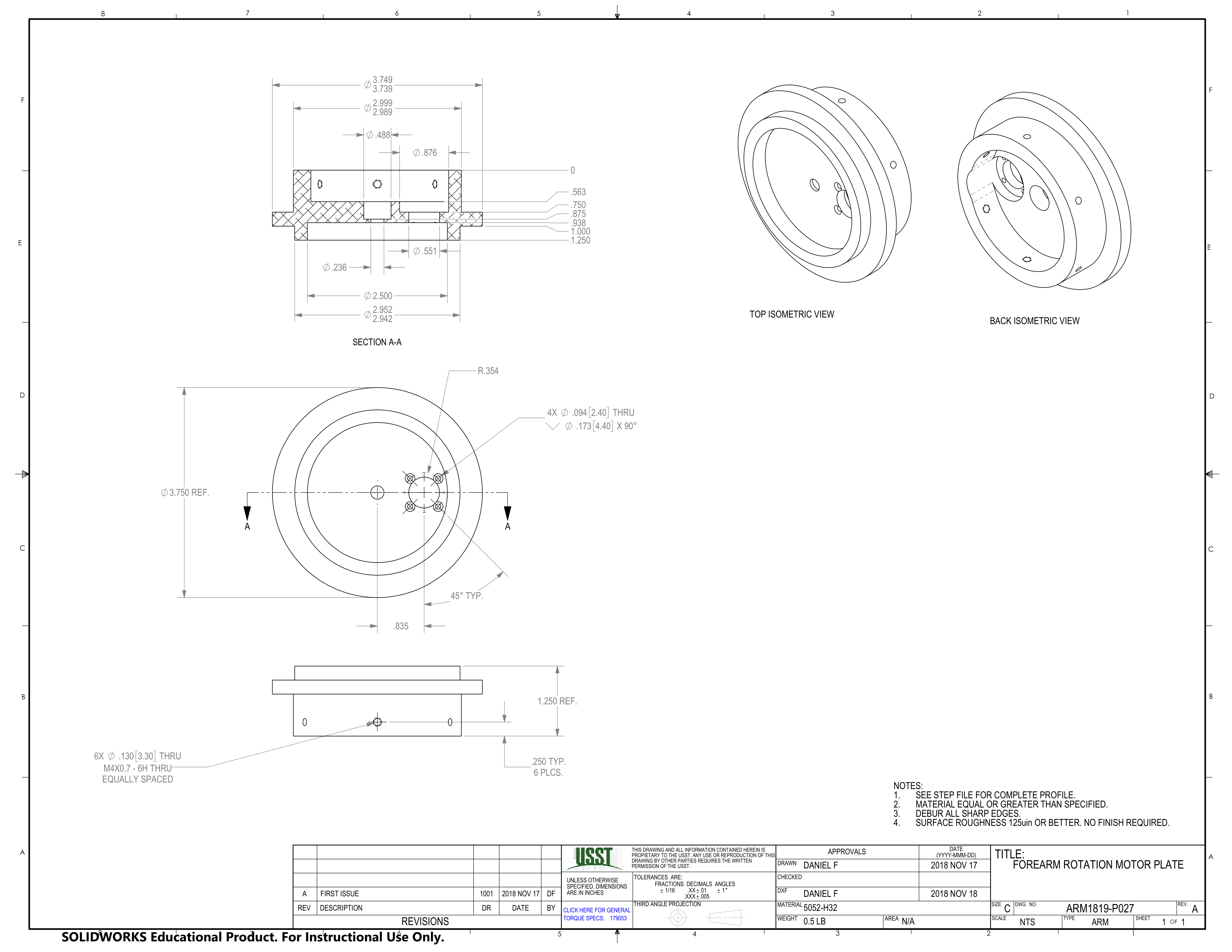
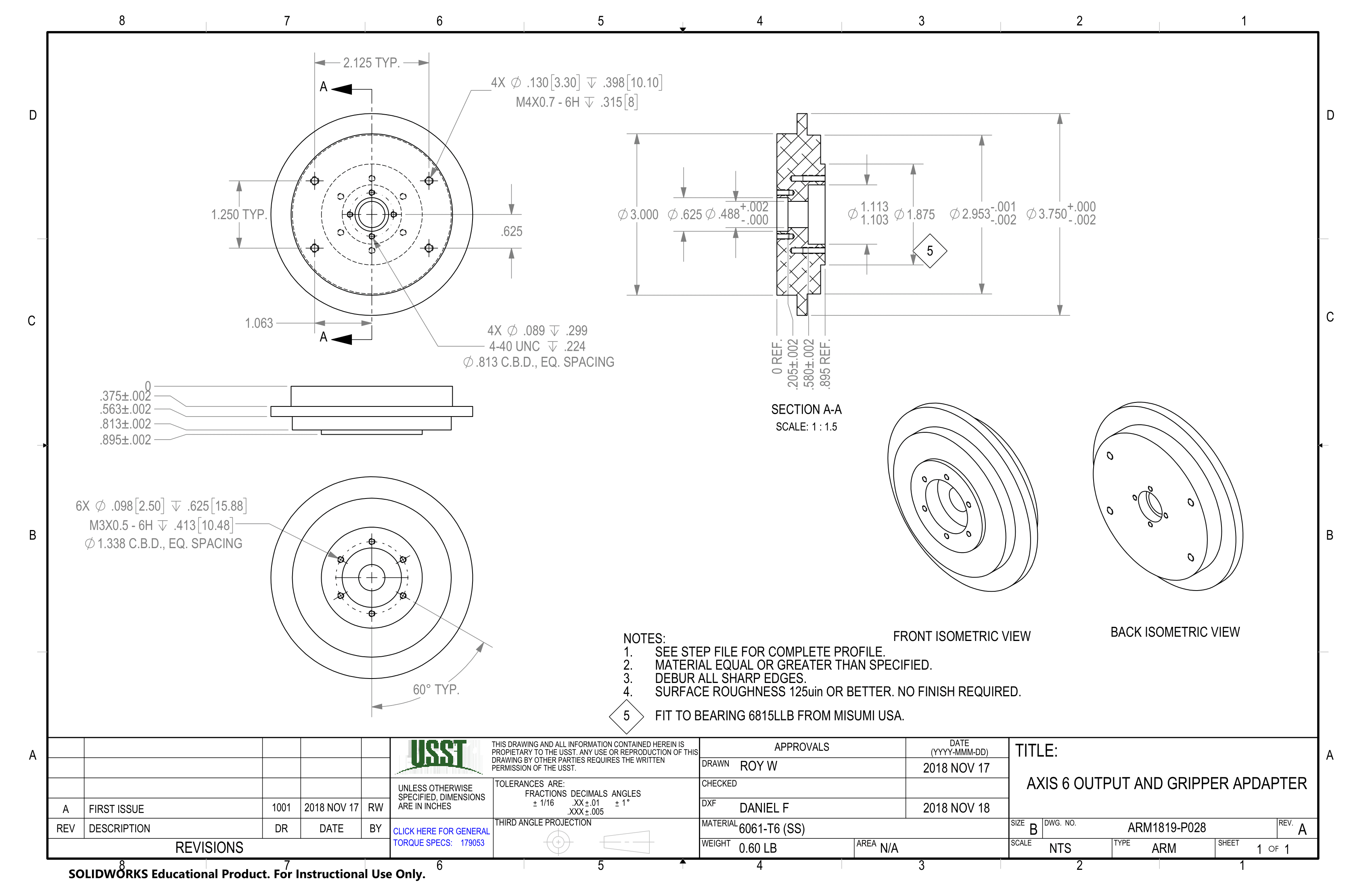
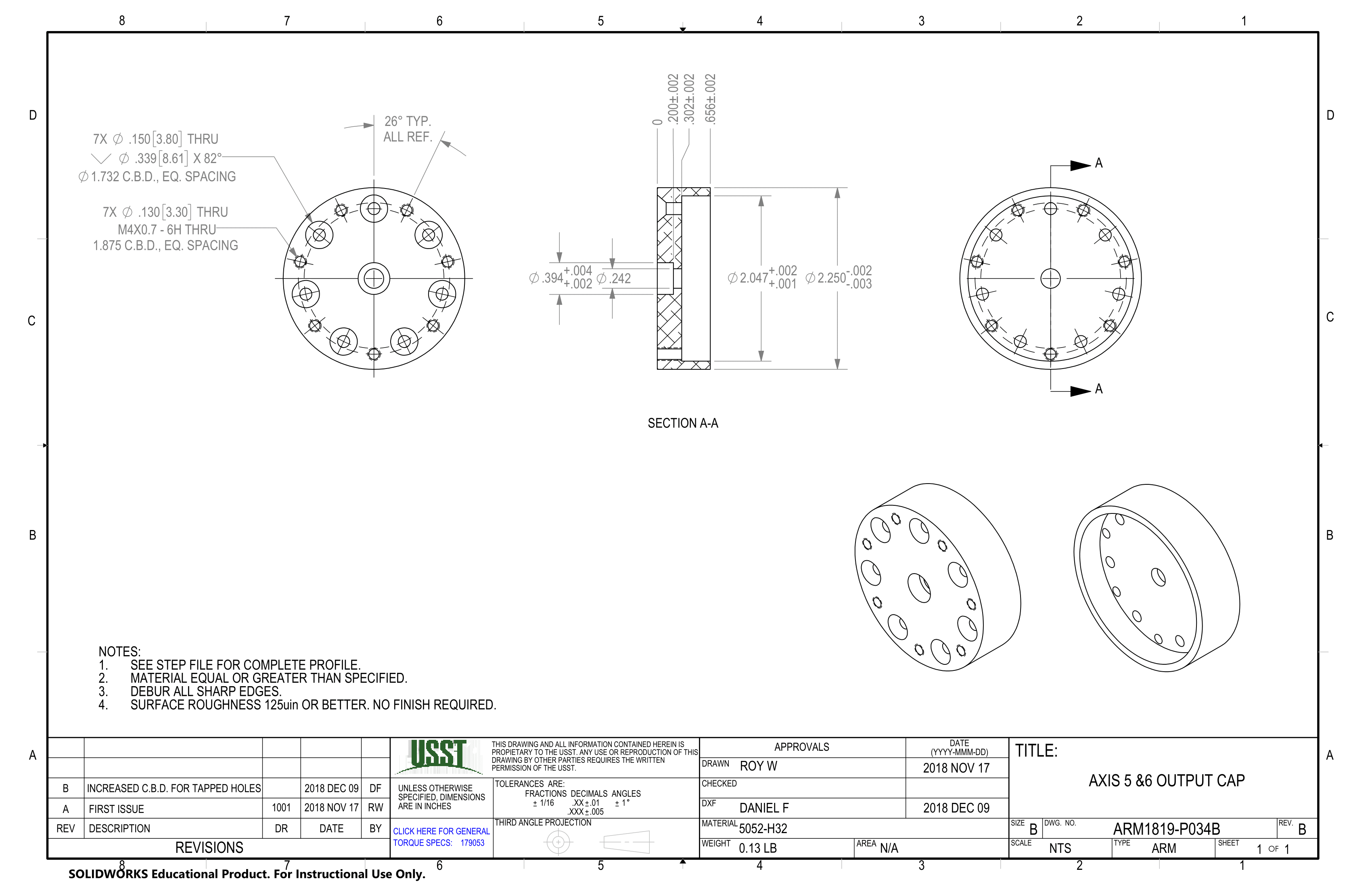
Drawings
Below are some of the drawings developed to assist in the fabrication of the CNC machined parts. The drawings hold the role of communicating fits and tolerances of parts to ensure proper fit during assembly and service.