2U CubeSat Frame Design
Introduction
 For my Fourth Year Design
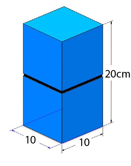
Project, or Capstone Project, my team and I were tasked with designing the frame of a 2U cube satellite,
or CubeSat, with dimensions of 10x10x20cm for the University of Saskatchewan Space Team (USST). The
USST’s CubeSat, RADSAT-SK, Saskatchewan’s first home-grown satellite, is expected to launch in the Fall
of 2021. CubeSats offer quick, cost-effective, and standardized means of gaining access to space for
research. The payload of the CubeSat will be testing radiation sensors and radiation shielding.
For my Fourth Year Design
Project, or Capstone Project, my team and I were tasked with designing the frame of a 2U cube satellite,
or CubeSat, with dimensions of 10x10x20cm for the University of Saskatchewan Space Team (USST). The
USST’s CubeSat, RADSAT-SK, Saskatchewan’s first home-grown satellite, is expected to launch in the Fall
of 2021. CubeSats offer quick, cost-effective, and standardized means of gaining access to space for
research. The payload of the CubeSat will be testing radiation sensors and radiation shielding.
Check out the full report: CubeSat Primary
Frame Design
Project Background
Current commercial off the shelf
units do not easily accommodate the addition of secondary structure components such as attitude
determination systems, inhibit switches, or antennas. Additionally, off the shelf units are difficult to
service requiring complete disassembly of the frame. Although off the shelf units are lightweight, their
cost is hard to justify.
The problem statement was created: a primary structure is required to maintain the structural integrity
of a CubeSat, which must interface and securely retain all internal components of the CubeSat while
meeting all requirements for spaceflight.
The selected design should increase the ease of assembly and serviceability of the CubeSat while finding
a balance between manufacturing costs and reducing the overall frame mass. It is expected that the
CubeSat will be assembled and disassembled roughly 25 times before flight, meaning an easily serviceable
and simple design is critical. Below are the six objectives and their metrics, to measure how well the
objective is met:
Major constraints include adhering to requirements outlined by the launch provider, NanoRacks. NanoRacks specifies several design driving features such as geometric tolerancing, surface hardness, and minimum strength requirements. Additionally, the design must accommodate client needs.
The Design
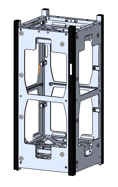
To achieve the goal of improving the serviceability of the CubeSat, our team 3-D printed a commercially available frame design. When we assembled the off the shelf unit we noticed that it was cumbersome to assemble and service the frame due to the number of parts, number of fasteners, and number of operations required to access the payload (the frame had to be completely disassembled!). It was noticed that many of the objectives can be met if the number of parts, unique parts, and fasteners are minimized.
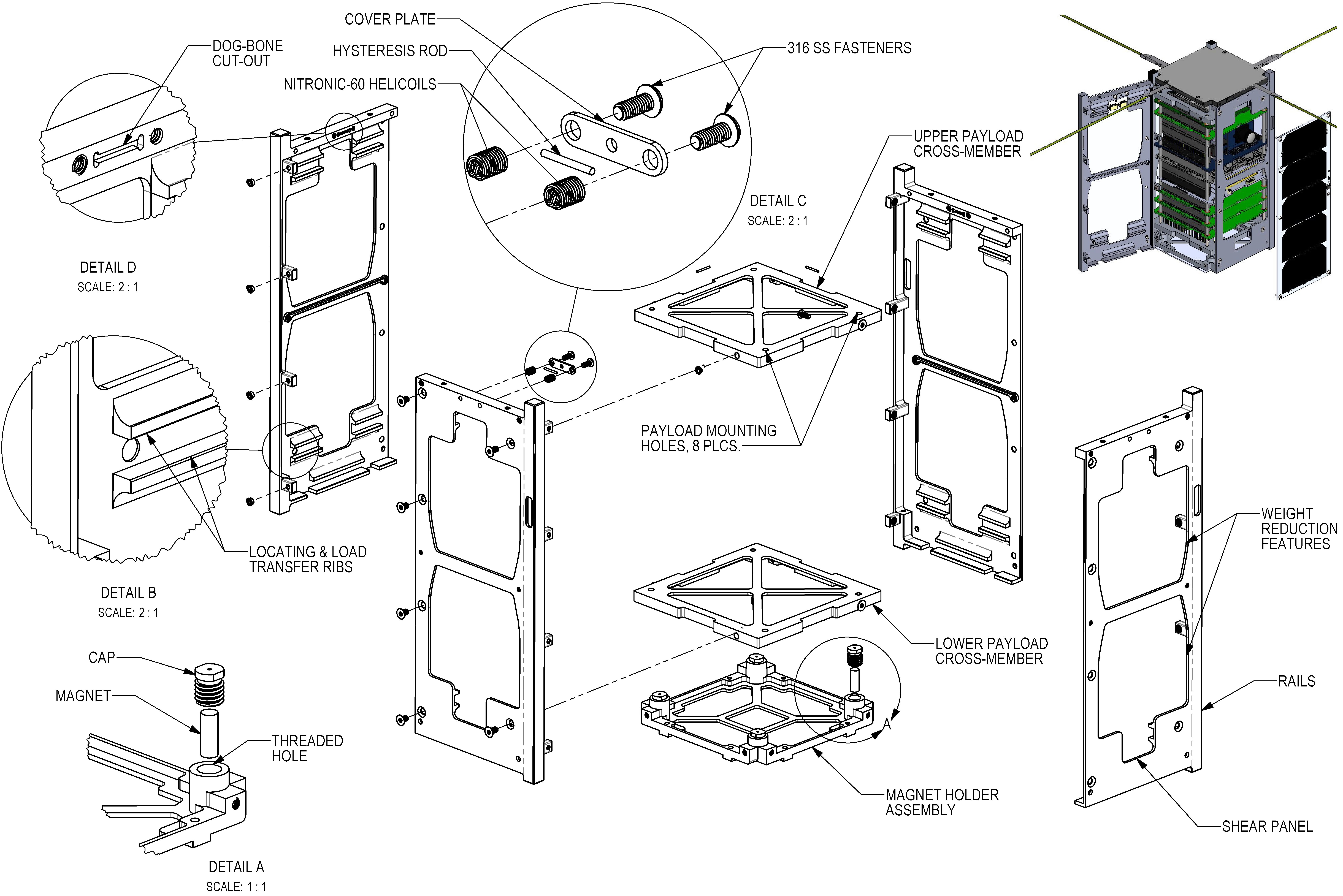
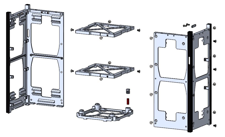
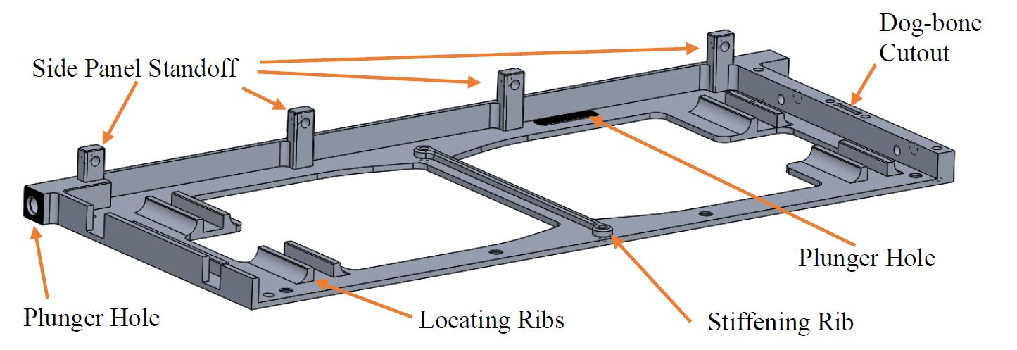
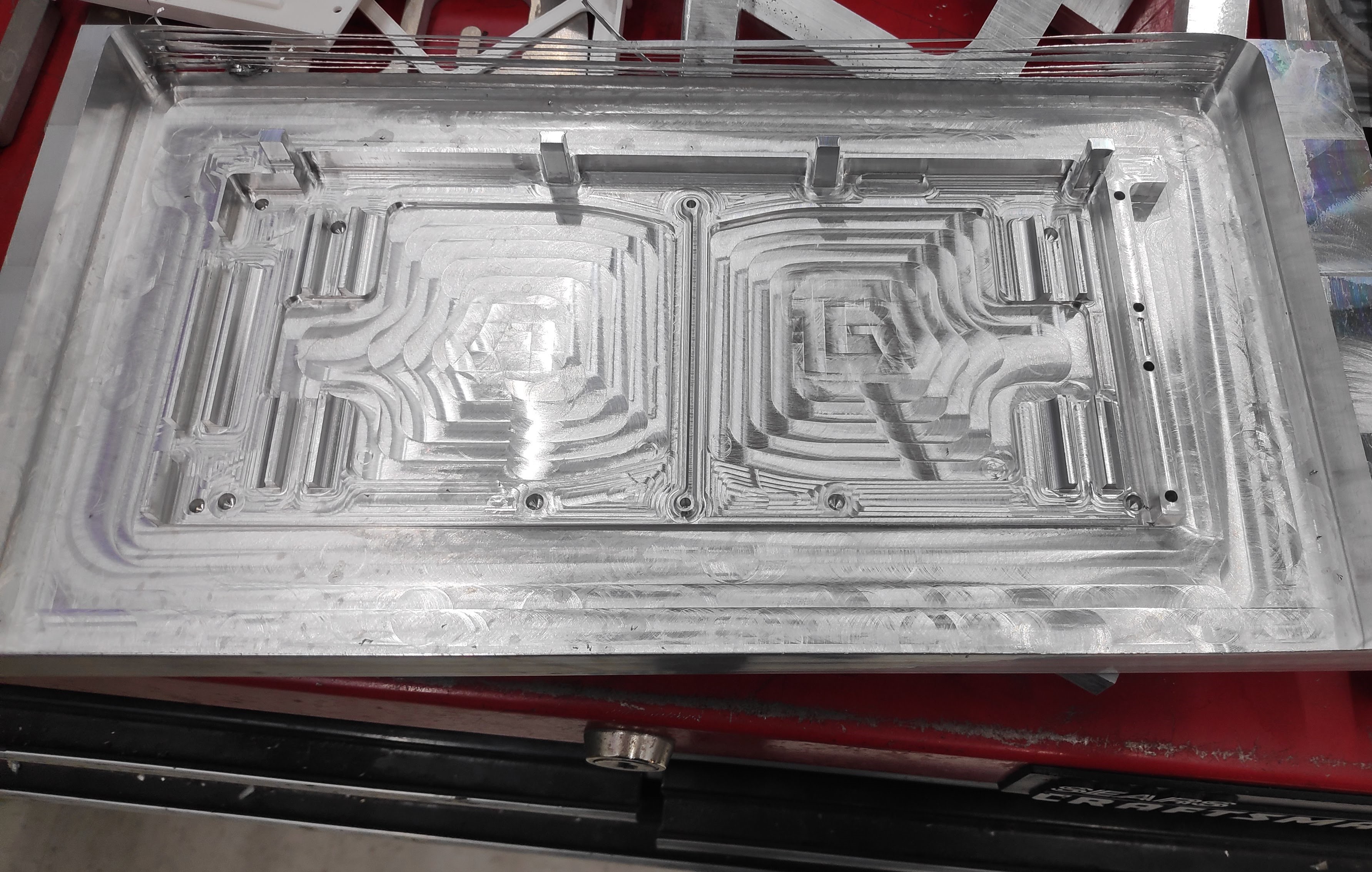
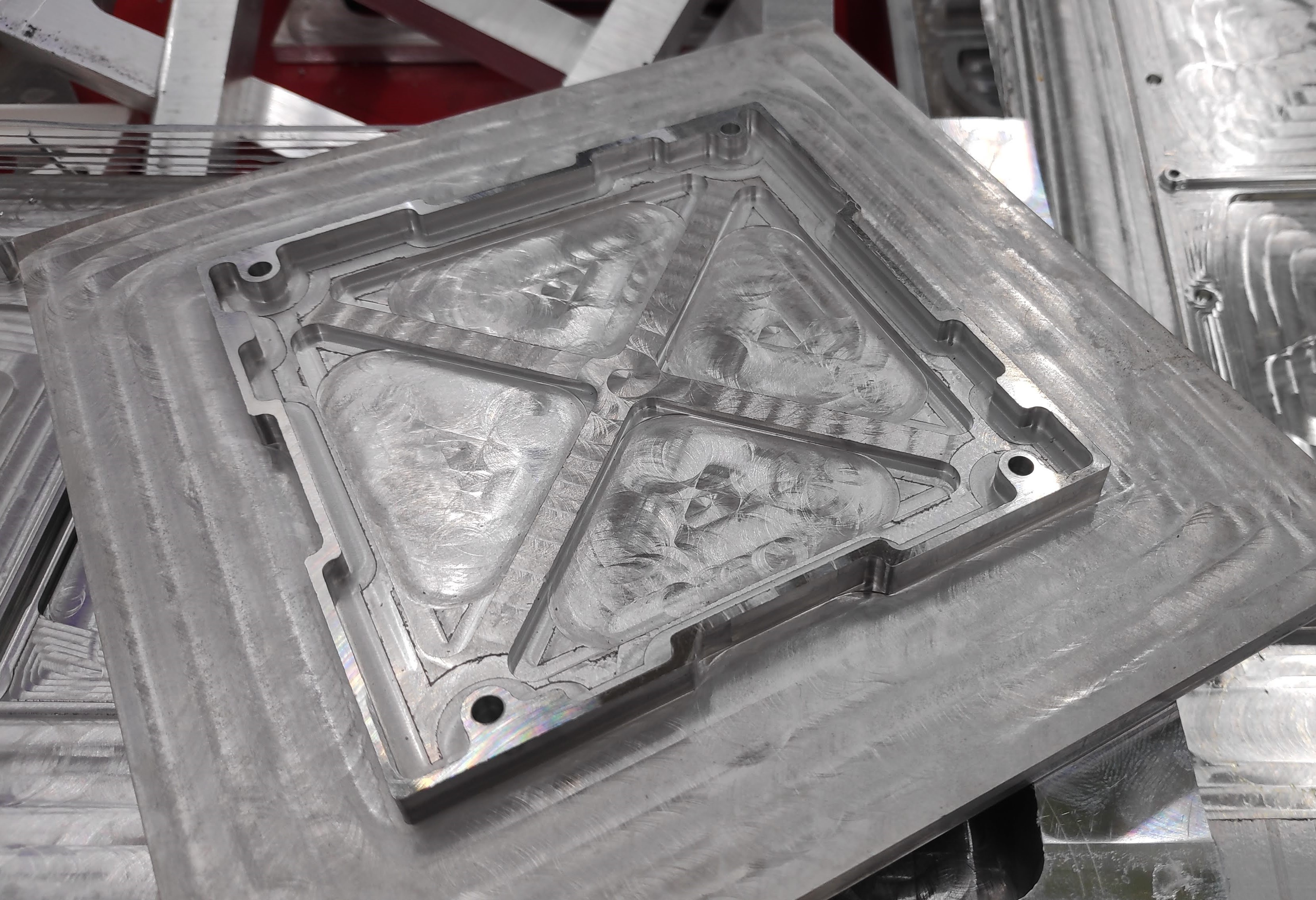
The side panels feature the integration of a shear panel and vertical rails to reduce the number of parts and the number of fasteners. Less parts and fasnteners aid to simplify the assembly of the frame. The side panels, made from 6061-T6 aluminum, are made identical to reduce the number of unique parts and result in a complex and multi-functional part. The standoffs are used to fasten two side panels at right angles. The locating ribs assist with assembly and improve the stiffness of the CubeSat. The "dog-bone cut-out" is a feature to retain a hysteresis rod, required for the attitude determination systems. The side panels will also secure the external solar panels and antenna, using Nitronic-60 SS threaded inserts (helicoils) to preserve the aluminum. The panels have an individual mass of 64.2 grams.
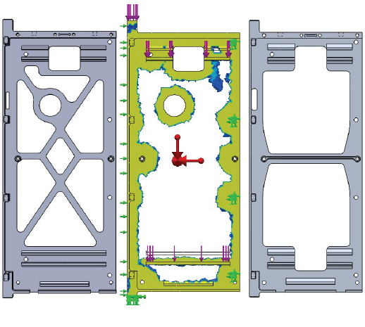
During the conceptual design phase, a geometrically artistic side panel design was developed (below, left). There was no mathematical reason for the geometry developed. During the detailed design phase, SolidWorks Topology Optimization was used to determine the minimum material requirements (below, center). The topology optimization indicated that the geometric cut-outs provided little structural support based on the forces the frame will experience. Based on a buckling analysis, a single brace and a stiffening rib was retained to improve confidence in the design. Removing the geometric cut-outs realized a 14.5% mass savings.
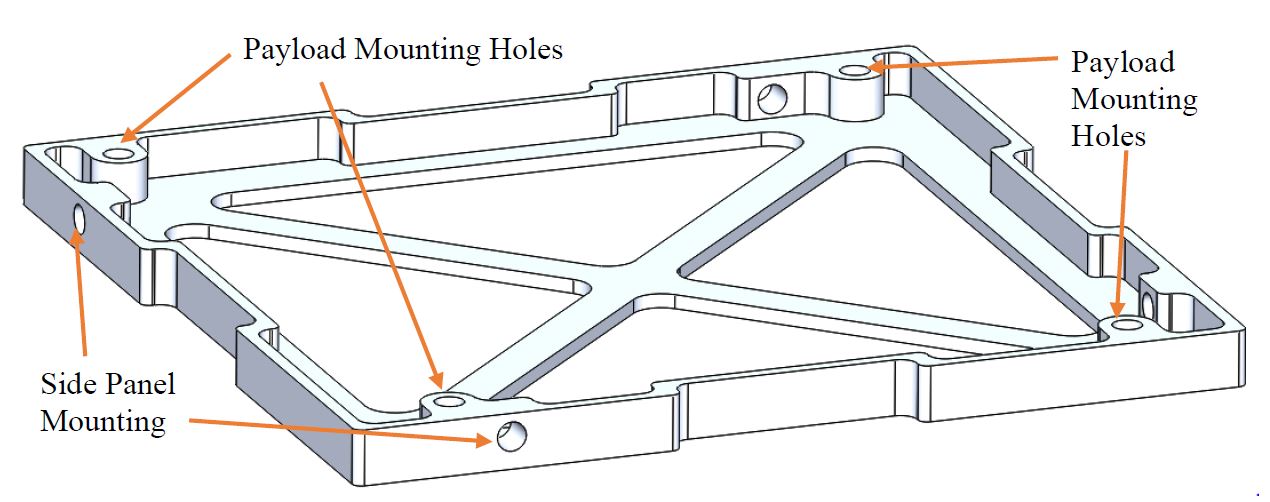
The payload, a stack of PCB's, will be sandwiched between two square cross members, shown below. The payload will be connected to the four holes on the top of the cross member. The cross member will be made from 6061-T6 aluminum and have an individual mass of 25.5 grams. The cross member will locate in the ribs on the side panels and will be secured with a single fastener per side.
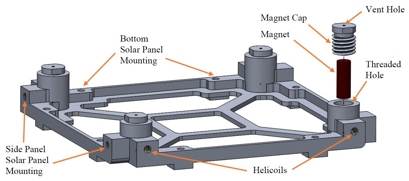
The client required a method for retaining four magnets, required for the attitude determination systems. The four magnets are held within the magnet holder assembly, shown below. The magnet holder cross member and magnet caps will both be made from 6061-T6 aluminum. The mass of the magnet cross member is 38.5 grams. This assembly will locate into ribs on the side panels and will be secured by 8 fasteners. A solar panel can be mounted on the bottom of the assembly via four more fasteners.
Results
Conclusions
This brief overview does not come close to doing justice the 723 hours my team and I spent working on this project. Through an iterative and creative design process, a design that is unique from off the shelf products was achieved. By having integrated rails and shear panels, the number of unique parts was greatly reduced. Adding locating ribs reduced the number of fasteners, the ease of assembly, and improved the frame rigidity. The frame will experience a maximum deflection of 0.309 mm and a maximum stress of 68.4 MPa. The design adheres to the many requirements outlined by the launch provided, NanoRacks, and by the client, the USST. My team places high confidence in the success of the design from a practical, iterative design approach and rigorous analysis.
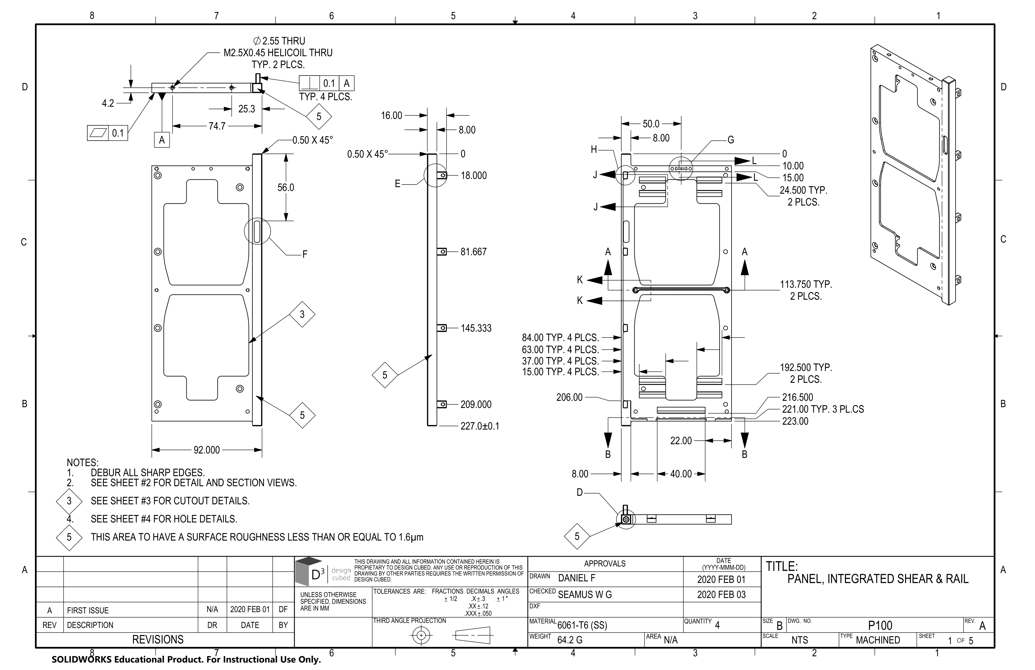
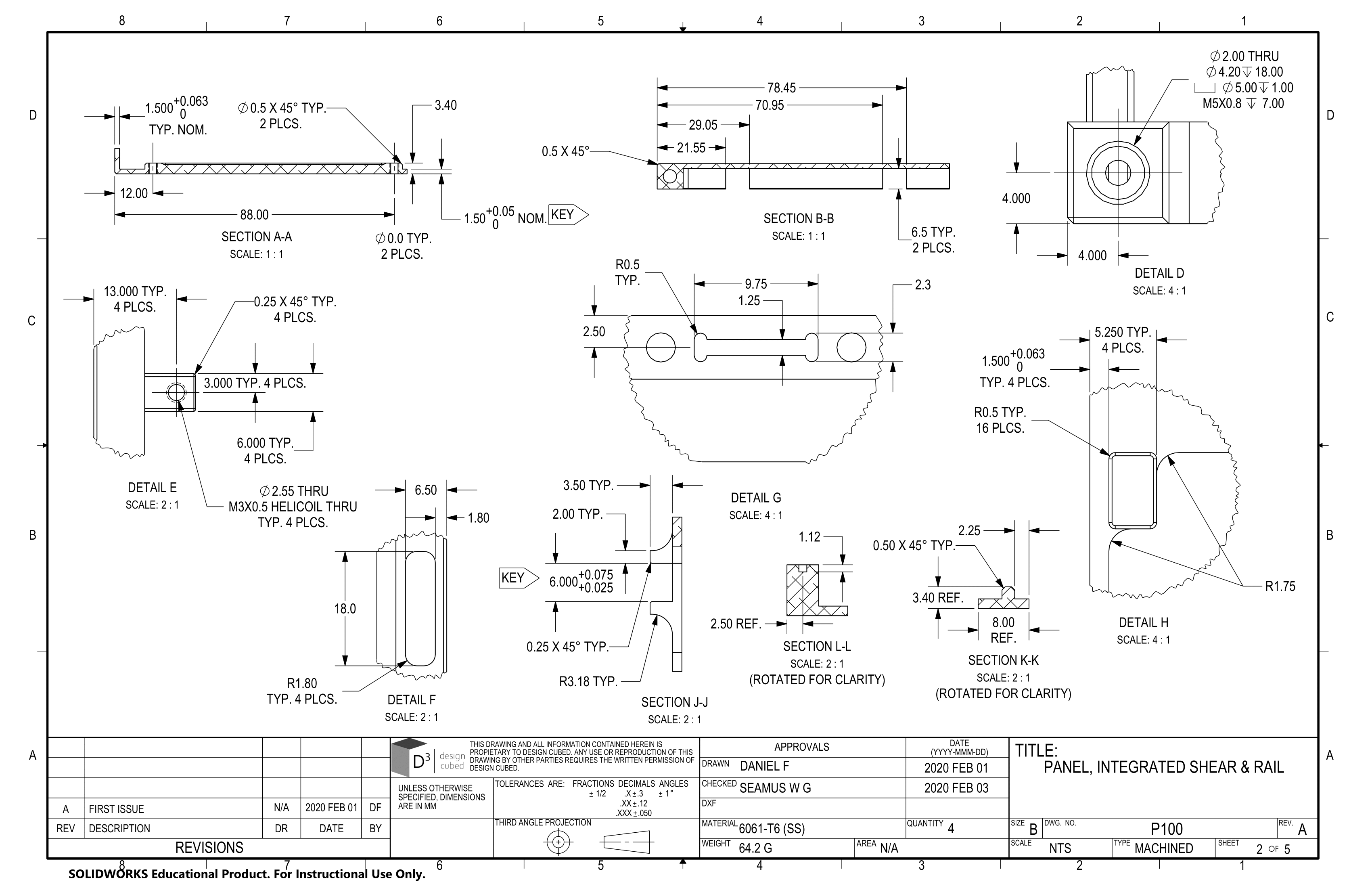
Drawings
Below are some of the drawings developed to assist in the fabrication of the prototype frame. The drawings hold the role of communicating fits and tolerances of parts to ensure proper fit during assembly and service.
Acknowledgements
I want to acknowledge: